Lull 6K Service Manual User Manual
Page 437
Boom and Transfer
Service Manual — Models 644B, 6K, 844C, 8K, 1044C, 10K
6-187
For Models 1044C-54 (S/N 144–) and 10K-54 (S/N 104–):
Use two (2) each nuts (Item 14), flatwashers (Item 7), and
capscrews (Item 6) to secure extension cylinder base mount
(Item 11) to rear of outer boom section. Install as many shims
(Items 12 and 13) as necessary before installing the nuts. Torque
nuts to 680 ft-lbs.
c. Install two (2) hydraulic tubes (Item 9) on extension cylinder elbows
(Item 8). Torque swivel nuts on hydraulic tubes to 79–88 ft-lbs.
d. Install cushion clamp (Item 10) on each hydraulic tube as
described in Substep d under Step 2 on page 6-185.
4. Apply EP lithium based grease to the inside top surfaces of outer boom
section (slide pad slide areas).
5. Turn outer boom section over and place it in upright position on work
stands.
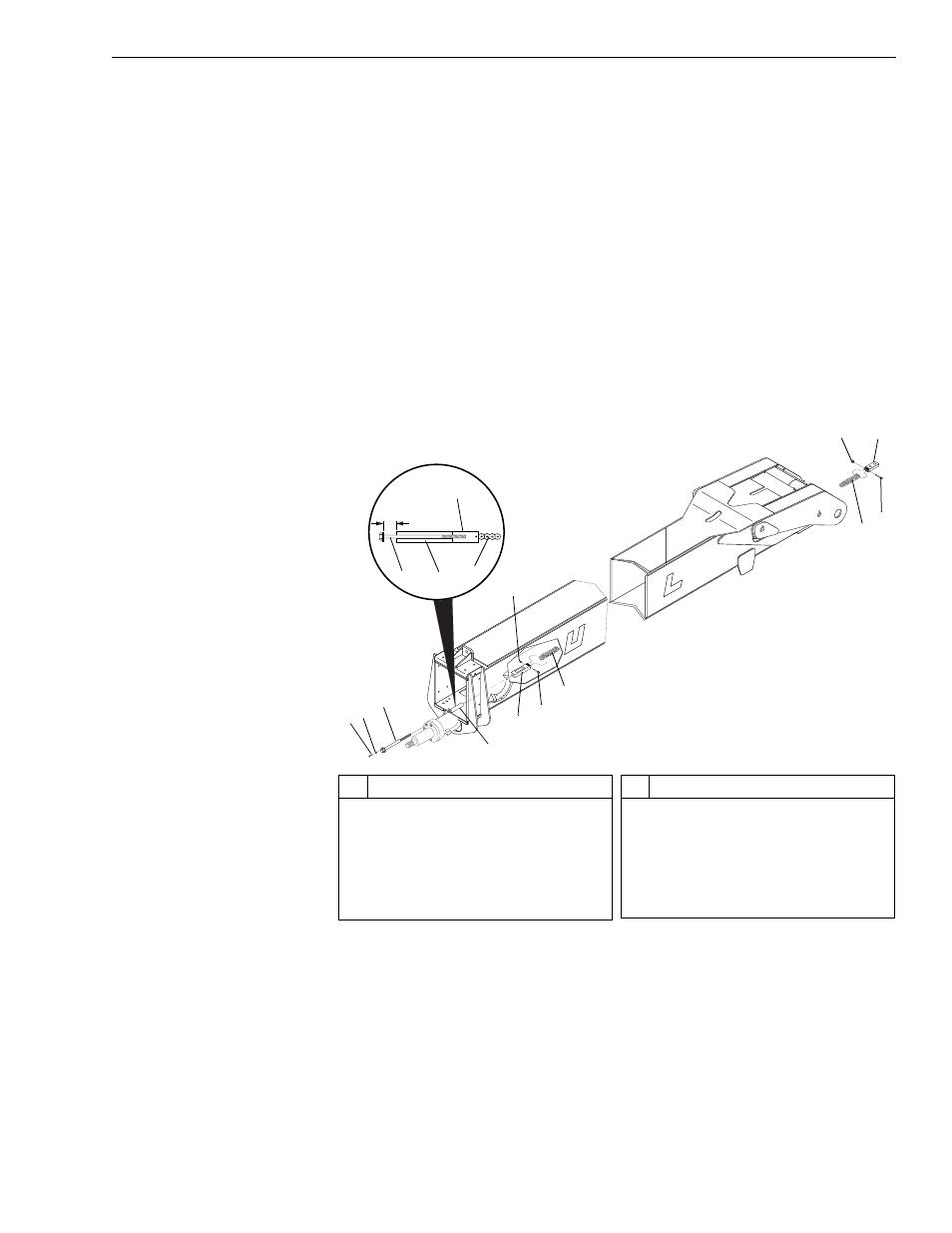
Fig. 6-201: Lower Chains on Outer Boom Section
6. (Ref. Fig. 6-201) Add lower chain to inside of outer boom section as
follows:
a. Install lower chain anchor (Item 10) on lower chain (Item 7) with
lock nut (Item 9) and shoulder bolt (Item 11). Torque lock nut to 108
in-lbs.
b. Install chain adjustment block (Item 5) on other end of lower chain
with shoulder bolt (Item 6) and lock nut (Item 8). Torque lock nut to
108 in-lbs.
0
80
60
40
20
-20
J
1242
#
Description
1
Capscrew
2
Lockwasher
3
Chain Adjustment Rod
4
Anchor Base
5
Chain Adjustment Block
6
Shoulder Bolt
#
Description
7
Lower Chain
8
Lock Nut
9
Lock Nut
10 Lower Chain Anchor
11 Shoulder Bolt
1
2
3
7
6
8
3
5
4
6
4
View A
3.13"
(3-1/8")
7
8
11
10
9