Lull 6K Service Manual User Manual
Page 506
Frame Tilt and Oscillation
7-4
Service Manual — Models 644B, 6K, 844C, 8K, 1044C, 10K
To level the frame, move the lever in the direction you want the ball in the
frame level indicator to move. Control is proportional: a small amount of
movement causes the frame to tilt slowly, while full movement of the
control causes faster frame movement.
Removal
Frame Tilt Control Valve
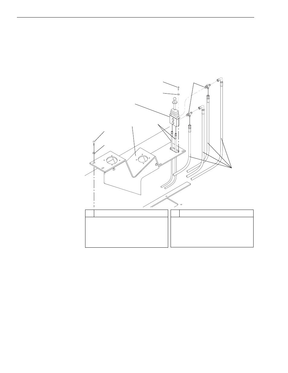
Fig. 7-3: Frame Tilt Control Valve Installation
(Ref. Fig. 7-3) The following procedure describes removal of the frame tilt
control valve.
1. Follow preparation procedures as outlined in Section 3 of this manual.
2. Remove six (6) screws (Item 2) and flatwashers (Item 1) securing
control panel (Item 3) to operator’s compartment. Lift up rear of control
panel to expose lower portion of frame tilt control valve (Item 5).
3. Tag and disconnect six (6) hydraulic hoses (Items 4 and 9) at frame tilt
control valve. Cap hoses and fittings.
Note: “K” Models have four hoses connected to the control valve.
4. Note Position of two (2) tee fittings (Item 8) on back side of valve body.
Remove fittings.
5
1
2
3
9
8
7
6
K
1
027
4
#
Description
1
Flatwasher
2
Screw
3
Control Panel
4
1/4” Hoses
5
Frame Tilt Control Valve
#
Description
6
Starwasher
7
Capscrew
8
Fittings
9
3/8” Hoses