Lull 6K Service Manual User Manual
Page 585
Brakes
Service Manual — Models 644B, 6K, 844C, 8K, 1044C, 10K
9-11
Disassembly
Service Brake Valve –
Models with Control
Manifold Hydraulics
6K-37 (S/N 101–317)
6K-42 (S/N 101–119)
8K-42 (S/N 101–220)
10K-42 (S/N 101–106)
10K-54 (S/N 101–103)
644B-37 (S/N 101–590, 592–666)
644B-42 (S/N 101–207)
844C-42 (S/N 101–521)
1044C-42 (S/N 101–116)
1044C-54 (S/N 101–154)
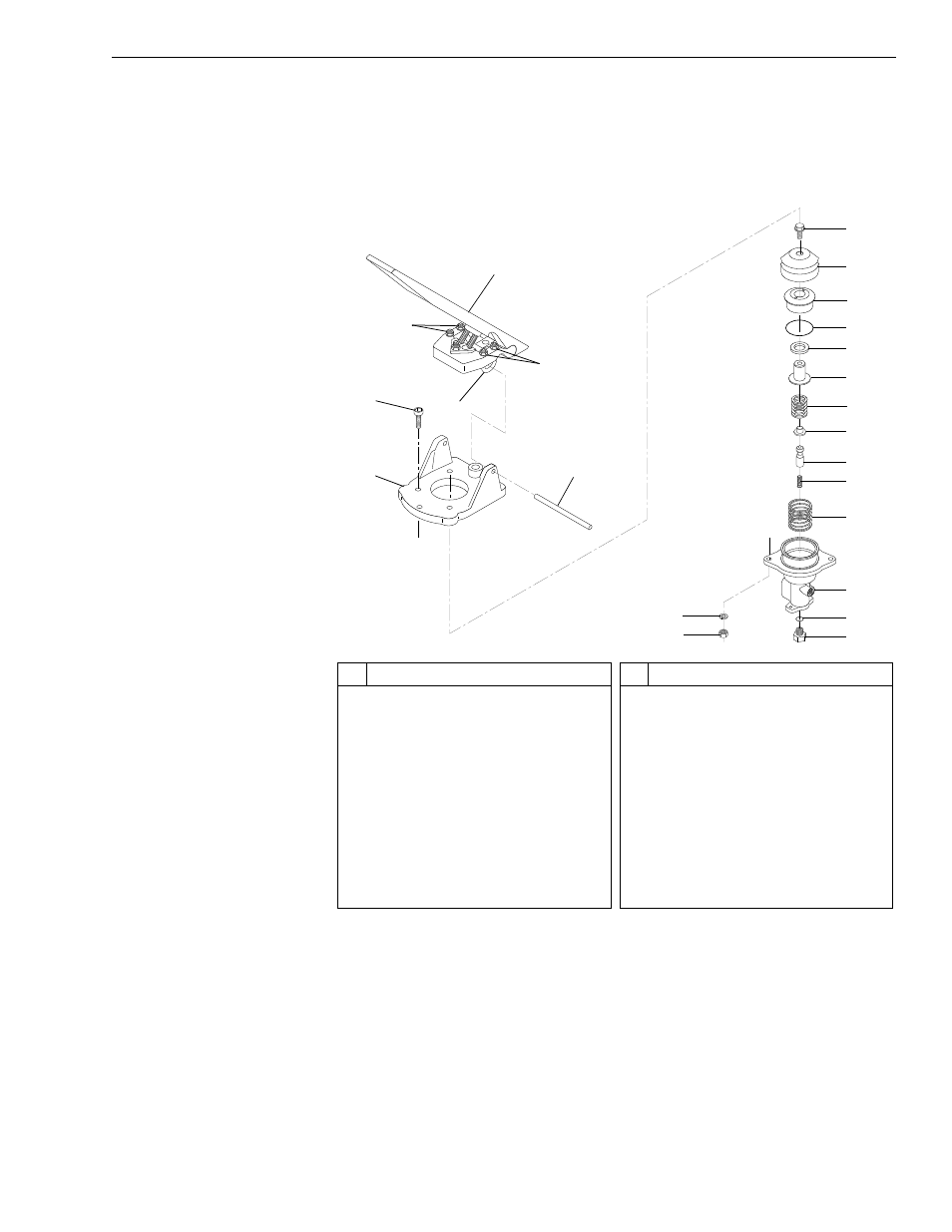
Fig. 9-7: Service Brake and Valve Assembly – Models with Control Manifold
Hydraulics
The following disassembly procedure refers to Fig. 9-7.
1. Loosen and remove flange head capscrew (Item 7) along with other
brake valve assembly parts (Items 8–17).
2. Remove the thread sealant from the flange head capscrew and piston
(Item 12).
3. Loosen and remove port adapter (Item 20) and O-ring (Item 19) from
brake valve body.
#
Description
1
Brake Pedal
2
Hex Nut
3
U-Clamp
4
Socket Head Capscrew
5
Actuator Base
6
Pedal Mounting Pin
7
Flange Head Capscrew
8
Rubber Boot
9
Piston Guide
10 O-Ring
11 Seal
#
Description
12 Piston
13 Regulator Spring
14 Spring Seat
15 Spool
16 Spool Return Spring
17 Piston Return Spring
18 Body
19 O-Ring
20 Port Adapter
21 Lockwasher
22 Hex Jam Nut
08-900
1
1
2
2
4
5
6
8
7
10
9
11
12
13
14
15
16
17
18
19
20
21
22
3