Lull 6K Service Manual User Manual
Page 620
Outriggers
10-2
Service Manual — Models 644B, 6K, 844C, 8K, 1044C, 10K
Removal
Outriggers
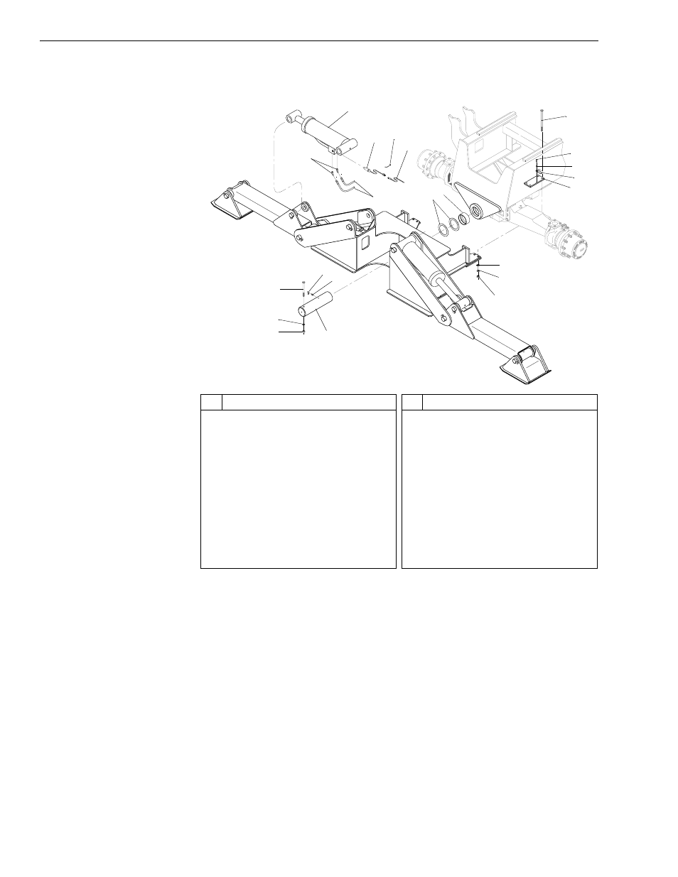
Fig. 10-2: Outrigger Installation
(Ref. Fig. 10-2) The following procedure describes removal of the
outrigger.
1. Follow preparation procedures as outlined in Section 3 of this manual.
2. Disconnect any attachments and raise the boom enough so easy
access can be made to the outrigger. Apply the parking brake and fully
retract the boom extension cylinder. Raise the outrigger foot pads
completely and shut the engine off.
3. Support the boom and extension cylinder with sling(s) and crane or
other suitable means. Make sure support items have sufficient capacity
to support the weight of the boom and cylinder; the combined weight of
the boom and extension cylinder is approximately 6650 pounds.
V
1085
#
Description
1
Outrigger Cylinder
2
Differential Pressure Switch
3
Tie
4
Wiring Harness
5
Elbow
6
Hydraulic Hose
7
Shim(s)
8
Outrigger Support Plate Bushing
9
Capscrew
10 Capscrew
11 Lockwasher
#
Description
12 Double Tube Clamp
13 Clamp Plate
14 Jam Nut
15 Starwasher
16 Nut
17 Shaft Assembly
18 Nut
19 Lockwasher
20 Capscrew
21 Grease Fitting
22 Grease Fitting Cover
20
19
18
17
22
16
15
14
7
13
12
11
10
9
1
2
3
5
6
21
4
8