Lull 6K Service Manual User Manual
Page 319
Boom and Transfer
Service Manual — Models 644B, 6K, 844C, 8K, 1044C, 10K
6-69
5. (Ref. Fig. 6-67) Look through the rear of the boom. Using a 12-inch
straight edge, measure the top surface of the rear of the inner boom
section. Maximum allowable deflection at the center, top of the inner
boom section is 1/4" (0.25").
Removal
2-Section Boom
1. Remove Quick Attach. See page 6-58.
2. Fully retract boom and transfer carriage (if equipped), lower boom to
ground.
3. Park machine on firm, level surface. Set park brake, lock shift selector
in NEUTRAL position, shut off engine and remove ignition key from
switch. Block all wheels.
4. Position crane next to machine.
5. Remove boom proximity switch. See “Boom Elevation Proximity
Switch” in Section 7.
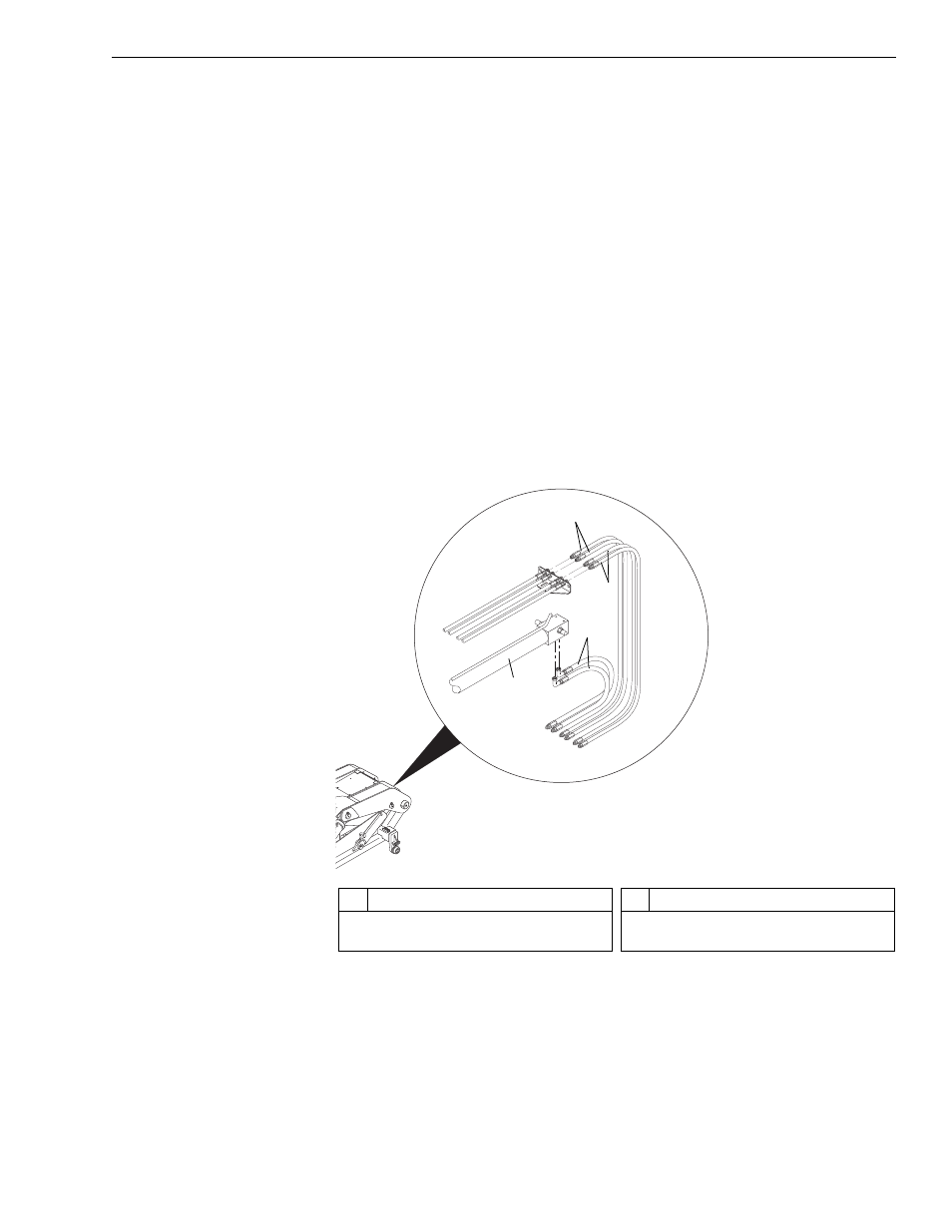
Fig. 6-68: Hose Connections, 2-Section Boom
6. (Ref. Fig. 6-68) Tag and disconnect two (2) hoses (Item 3) at the boom
extension cylinder (Item 4). Cap hoses and fittings.
7. (Ref. Fig. 6-68) Tag and disconnect two (2) carriage tilt hoses (Item 2),
and two (2) auxiliary hydraulics hoses (Item 1) at the boom. Cap hoses
and fittings.
J1071
1
2
3
4
#
Description
1
Auxiliary Hydraulic Hoses
2
Carriage Tilt Hoses
#
Description
3
Boom Extension Hoses
4
Boom Extension Cylinder