Lull 6K Service Manual User Manual
Page 181
Supply, Pressure, and Return Hydraulics
Service Manual — Models 644B, 6K, 844C, 8K, 1044C, 10K
5-37
Models with Mid-Inlet Hydraulics
6K-37 (S/N 318–)
6K-42 (S/N 120–)
8K-42 (S/N 221–)
10K-42 (S/N 107–)
10K-54 (S/N 104–)
644B-37 (S/N 591, 667–)
644B-42 (S/N 208–)
844C-42 (S/N 622–)
1044C-42 (S/N 117–)
1044C-54 (S/N 155–)
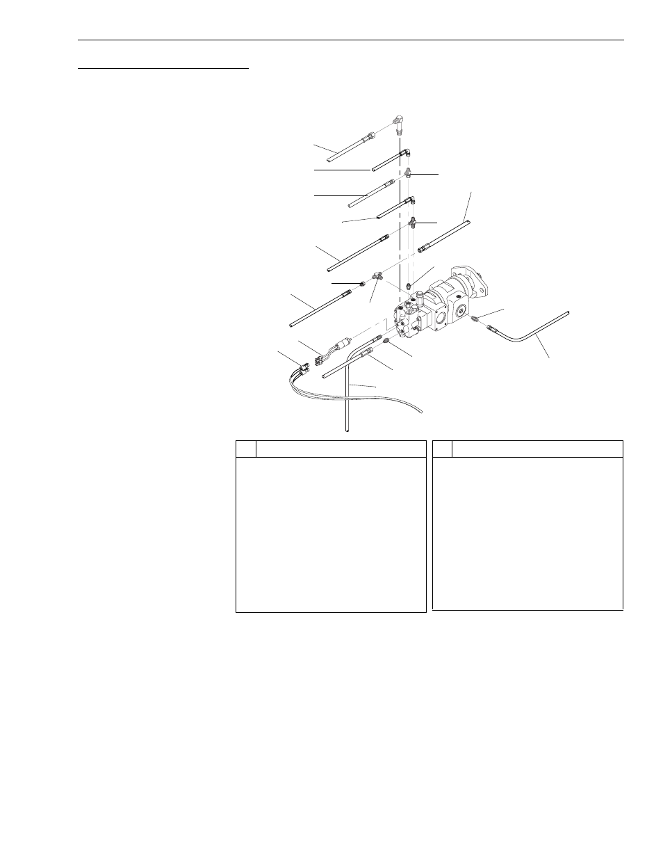
Fig. 5-25 and Fig. 5-26 describe procedures for removal of the hydraulic
pump for models with a mid-inlet hydraulic system.
Fig. 5-25: Hydraulic Pump Hoses – Mid-Inlet Hydraulics
(Ref. Fig. 5-25) The following describes initial steps for removal of the
hydraulic pump.
1. Follow preparation procedures as outlined in Section 3 of this manual.
Be sure to follow the guidelines in this section detailed under “General
Hydraulic Maintenance Practices” on page 5-4.
2. Install brake pressure diagnostic port test gauge into brake diagnostic
port (see page 5-90).
3. While watching test gauge, press brake pedal numerous times until
pressure gauge reads 0 psi. Remove test gauge from diagnostic port.
#
Description
1
Hydraulic Hose to Valve Plate
2
Hyd. Hose to Steering Test Port
3
Hydraulic Hose to Valve Plate
4
Hydraulic Hose to Pilot Test Port
5
Hydraulic Hose to Accumulator
6
Reducer Adapter
7
Hyd. Hose to Pump 1 Test Port
8
Branch Tee
9
Pressure Switch
10 Intermediate Wiring Harness
11 Hydraulic Hose to Control Valve
#
Description
12 Hydraulic Hose to Accumulator
13 Connector
14 Hydraulic Hose to Elbow on Rear
Oscillation Lock Control Block
15 Check Valve
16 Connector
17 Run Tee
18 Hydraulic Hose to Check Valve on
Rear Oscillation Lock Control Blk
19 Swivel Run Tee
20 Long Elbow
K
1119
1
2
5
4
9
10
11
12
18
14
3
7
6
8
13
15
16
17
19
20