Service brakes – Lull 6K Service Manual User Manual
Page 575
Service Manual — Models 644B, 6K, 844C, 8K, 1044C, 10K
9-1
Section 9 — Brakes
Service Brakes
Description, Models with Control Manifold Hydraulics
6K-37 (S/N 101–317)
6K-42 (S/N 101–119)
8K-42 (S/N 101–220)
10K-42 (S/N 101–106)
10K-54 (S/N 101–103)
644B-37 (S/N 101–590, 592–666)
644B-42 (S/N 101–207)
844C-42 (S/N 101–521)
1044C-42 (S/N 101–116)
1044C-54 (S/N 101–154)
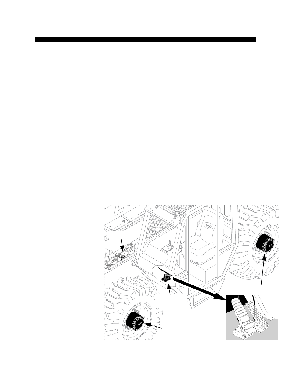
The service brakes are operated and controlled by hydraulic oil from the
hydraulic system. Fluid flows from the brake port of the control manifold to
the brake valve and on to the front and rear brakes. The service brake
system consists of:
1. Accumulator
2. Brake Pedal
3. Brake Valve
4. Disc Brakes.
The accumulator is located near the middle of the machine on the valve
plate. The brake pedal and valve is located on the floor of the cab. The disc
brakes are internally located in an oil bath within the wheel ends of the
axles. See Fig. 9-1.
Note: The axles must be disassembled to service the brake discs. Refer to the
axle manufacturer’s maintenance manual for overhaul procedures.
Fig. 9-1: Service Brakes
0
80
60
40
20
-20
V
1071
Accumulator
Brake Pedal
and Valve
Disc Brakes
Disc Brakes
H1009