Lull 6K Service Manual User Manual
Page 377
Boom and Transfer
Service Manual — Models 644B, 6K, 844C, 8K, 1044C, 10K
6-127
2). Secure cylinder stop to extension cylinder with capscrew
(Item 1), lockwasher (Item 3), and nut (Item 4) Torque nut to
276 in-lbs.
3). Torque the two (2) cylinder stop nuts (Item 7) to 276 in-lbs.
For all other models (see View B),
1). Install the cylinder stop (Item 11) on the boom extension
cylinder with a capscrew (Item 12), lockwasher (Item 13), and
nut (Item 14).
2). Torque the cylinder stop nut (Item 14) to 276 in-lbs.
b. Position the boom extension cylinder under the outer boom
section. Secure the boom extension cylinder to the boom with two
(2) lockwashers (Item 16) and capscrews (Item 15). Torque the
capscrews to 200 ft-lbs.
c. Install the cylinder support bracket (Item 8) on the outer boom
section using two (2) lockwashers (Item 9) and capscrews
(Item 10). Torque the capscrews to 55 ft-lbs.
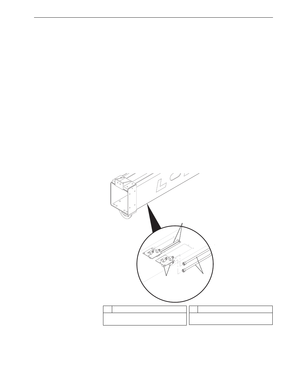
d. Install the two (2) hydraulic tubes (Item 17) on the manifold block of
the boom extension cylinder (Item 18). Torque the hydraulic tube
swivel nuts to 79–88 ft-lbs.
22. Cap hoses and fittings.
Fig. 6-135: Hydraulic Tube Installation, Outer Boom
J
109
2
#
Description
1
Swivel Elbows
2
Auxiliary Hydraulic Tubes
#
Description
3
Carriage Tilt Tubes
2
1
3