Lull 6K Service Manual User Manual
Page 179
Supply, Pressure, and Return Hydraulics
Service Manual — Models 644B, 6K, 844C, 8K, 1044C, 10K
5-35
Removal
Hydraulic Pump
Models with Control Manifold Hydraulics
6K-37 (S/N 101–317)
6K-42 (S/N 101–119)
8K-42 (S/N 101–220)
10K-42 (S/N 101–106)
10K-54 (S/N 101–103)
644B-37 (S/N 101–590, 592–666)
644B-42 (S/N 101–207)
844C-42 (S/N 101–621)
1044C-42 (S/N 101–116)
1044C-54 (S/N 101–154)
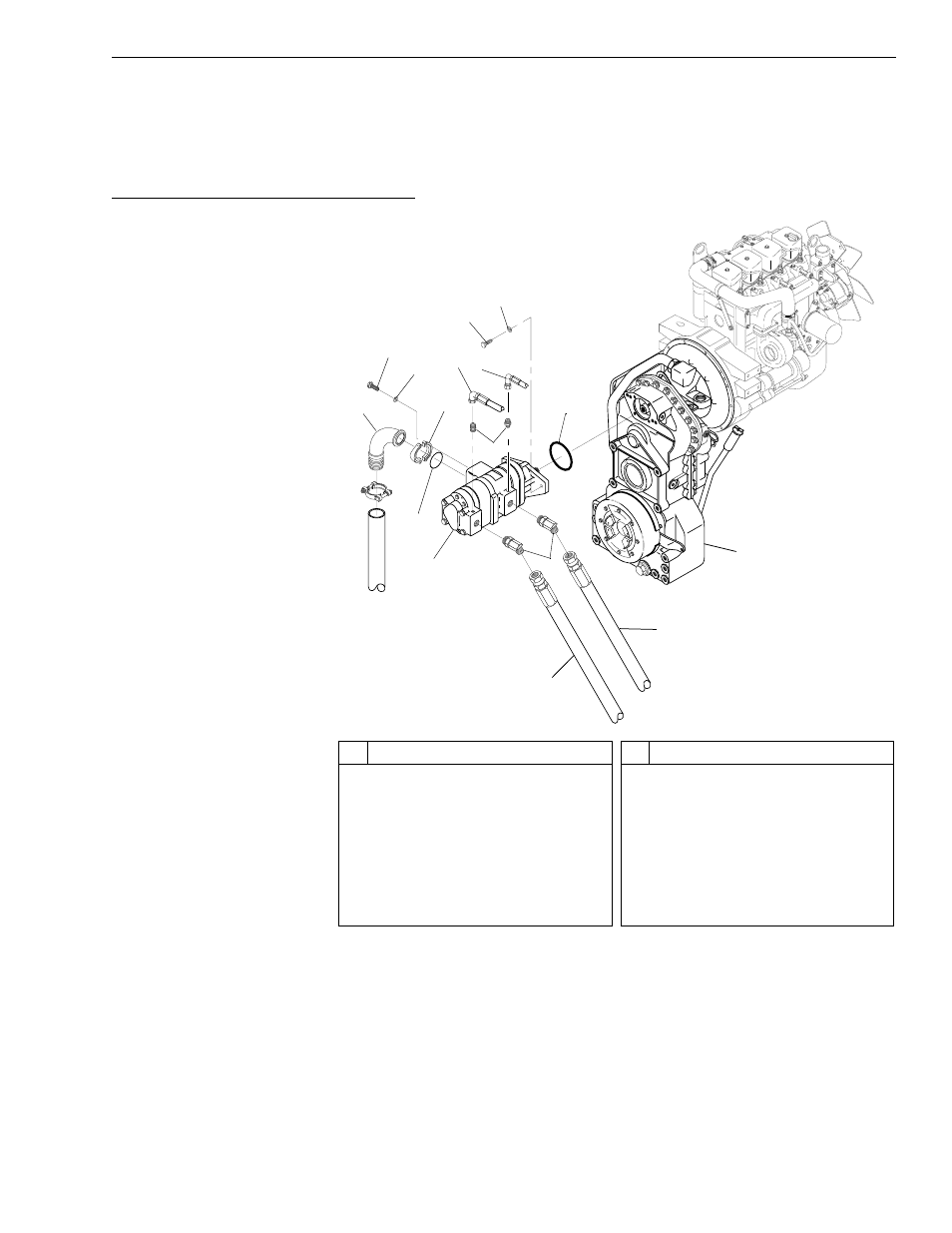
Fig. 5-24: Hydraulic Pump Installation – Control Manifold Hydraulics
(Ref. Fig. 5-24) The following steps are required to remove the hydraulic
pump for models with control manifold hydraulics.
1. Follow preparation procedures as outlined in Section 3 of this manual.
Be sure to follow the guidelines in this section detailed under “General
Hydraulic Maintenance Practices” on page 5-4.
2. Install brake pressure diagnostic port test gauge into brake diagnostic
port (see page 5-90).
#
Description
1
Elbow Flange Head Connector
2
Capscrew
3
Lockwasher
4
Flange Half
5
Hydraulic Hose
6
Hydraulic Hose
7
Capscrew
8
Lockwasher
#
Description
9
Connector
10 O-Ring
11 Transmission
12 Hydraulic Hose
13 Hydraulic Hose
14 45° Elbow
15 Hydraulic Pump
16 O-Ring
K
1065
1
2
3
4
16
15
13
12
11
10
8
7
6
9
14
5