Lull 6K Service Manual User Manual
Page 546
Frame Tilt and Oscillation
7-44
Service Manual — Models 644B, 6K, 844C, 8K, 1044C, 10K
Removal
Boom Elevation Proximity
Switch
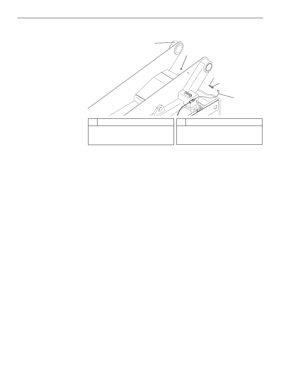
Fig. 7-28: Boom Elevation Proximity Switch Assembly
1. (Ref. Fig. 7-28) Disconnect wire harness (Item 5) at boom proximity
switch (Item 3).
2. Place a piece of masking tape around proximity switch body at the
outer jam nut (Item 4) (this will serve as a guide during re-installation).
3. Remove inner jam nut (Item 2) and proximity switch form transfer
carriage/boom cradle (Item 1). Re-install inner jam nut on proximity
switch for safekeeping.
Installation
Boom Elevation Proximity
Switch
1. Position outer jam nut (Item 4) on switch body (Item 3) at previously
marked position.
2. Install boom proximity switch in transfer carriage/boom cradle (Item 1).
Install inner jam nut (Item 2). Check gap between end of proximity
switch and boom. See Fig. 7-29.
3. Connect wire harness (Item 5) to proximity switch.
4. Check operation of proximity switch by raising the boom. The Rear
Osc Lock light must come on at approximately 40° of boom elevation.
If the light does not illuminate, stop and lower boom. Proceed to
“Adjustment” below.
J
1
074
1
2
4
3
5
#
Description
1
Transfer Carriage/Boom Cradle
2
Inner Jam Nut
3
Proximity Switch
#
Description
4
Outer Jam Nut
5
Wire Harness