Lull 6K Service Manual User Manual
Page 448
Boom and Transfer
6-198
Service Manual — Models 644B, 6K, 844C, 8K, 1044C, 10K
b. Install two (2) bulkhead adapters (Item 4) on rear of inner boom
section (Item 2).
c. Connect two (2) grease hoses (Item 1) to bulkhead adapters.
Torque swivel nuts on grease hoses to 130–150 in-lbs.
d. Connect grease hoses to elbows. Torque swivel nuts on grease
hose to 130–150 in-lbs.
e. Install grease fittings (Item 5) and grease fitting covers (Item 6) on
bulkhead adapters (Item 2). Torque grease fittings 2–3 turns past
finger tight.
28. Turn inner boom section over and place it on work stands in upright
position.
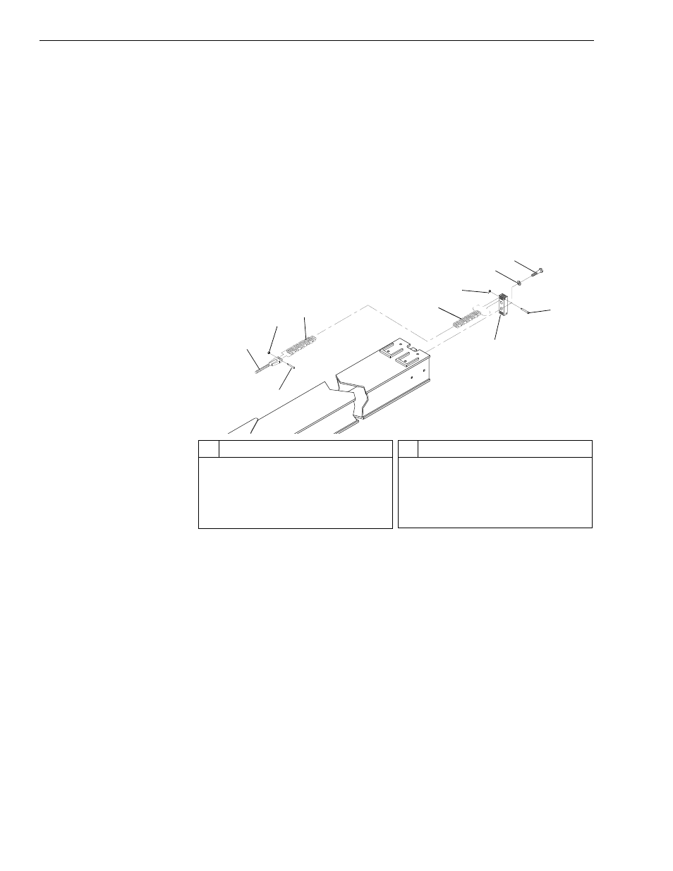
Fig. 6-212: Upper Chain Installation – Inner Boom Section
29. (Ref. Fig. 6-212) Install upper chain assembly on inner boom section
as follows:
a. Install rear chain anchor (Item 9) on inner boom section with two
(2) lockwashers (Item 6) and capscrews (Item 7). Torque
capscrews to 280 ft-lbs.
b. Install upper chain (Item 4) on chain anchor with shoulder bolt
(Item 8) and lock nut (Item 5). Torque lock nut to 108 in-lbs.
c. Install chain adjustment anchor (Item 1) on upper chain with
shoulder bolt (Item 3) and lock nut (Item 2). Torque lock nut to 108
in-lbs.
d. Lay upper chain flat on top of inner boom section.
30. Lift inner boom section and slide it into middle (front) boom section.
J
1248
8
6
1
7
2
3
4
5
9
4
#
Description
1
Chain Adjustment Anchor
2
Lock Nut
3
Shoulder Bolt
4
Upper Chain
5
Lock Nut
#
Description
6
Lockwasher
7
Capscrew
8
Shoulder Bolt
9
Rear Chain Anchor