Lull 6K Service Manual User Manual
Page 590
Brakes
9-16
Service Manual — Models 644B, 6K, 844C, 8K, 1044C, 10K
Service Brake Pressure Switch Replacement
Models with Control Manifold Hydraulics
6K-37 (S/N 101–317)
6K-42 (S/N 101–119)
8K-42 (S/N 101–220)
10K-42 (S/N 101–106)
10K-54 (S/N 101–103)
644B-37 (S/N 101–590, 592–666)
644B-42 (S/N 101–207)
844C42 (S/N 101–521)
1044C-42 (S/N 101–116)
1044C-54 (S/N 101–154)
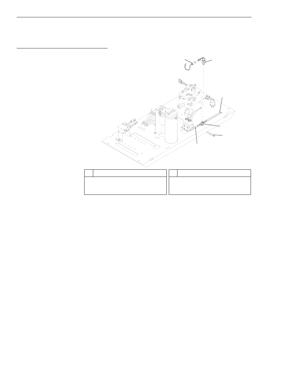
Fig. 9-10: Service Brake Pedal Pressure Switch – Control Manifold
Hydraulics
The service brake pedal pressure switch is located on the left side and
towards the rear of the valve plate (see Fig. 9-10). This switch is normally
open and is set to close above 250 psi.
1. Follow preparation procedures as outlined in Section 3 and in
Section 5 of this manual.
2. Tag and disconnect the wiring harness connector (Item 1) from the
connector on the brake pressure switch (Item 2).
3. Remove the brake pressure switch from the adapter fitting (Item 4).
Discard the pressure switch.
4. Install a new brake pressure switch (Item 2) on the adapter fitting
(Item 4). For final tightening, torque the pressure switch to
205–235 in-lbs.
5. Reconnect the wiring harness connectors (Item 1) to the connectors
on the brake pressure switch.
1
V
1073
6
3
2
4
5
#
Description
1
Wiring Harness Connector
2
Service Brake Pressure Switch
3
Hydraulic Hose
#
Description
4
Adapter Fitting
5
Brake Pedal Hydraulic Hose
6
Hydraulic Hose