Lull 6K Service Manual User Manual
Page 182
Supply, Pressure, and Return Hydraulics
5-38
Service Manual — Models 644B, 6K, 844C, 8K, 1044C, 10K
4. For models 644B, 844C, and 1044C, refer to roll-back hose tray
removal procedures on page 5-92.
5. Disconnect wiring harness (Item 10) from pressure switch (Item 9).
6. Thoroughly clean the hydraulic pump to ensure that dirt will not get into
the system/transmission.
7. Tag and
slowly loosen the ten (10) hydraulic hoses shown in Fig. 5-25
(Items 1 thru 5, 7, 11, 12, 14, and 18). Bleed any remaining oil into
appropriate container. Disconnect hoses. Cap fittings and hoses.
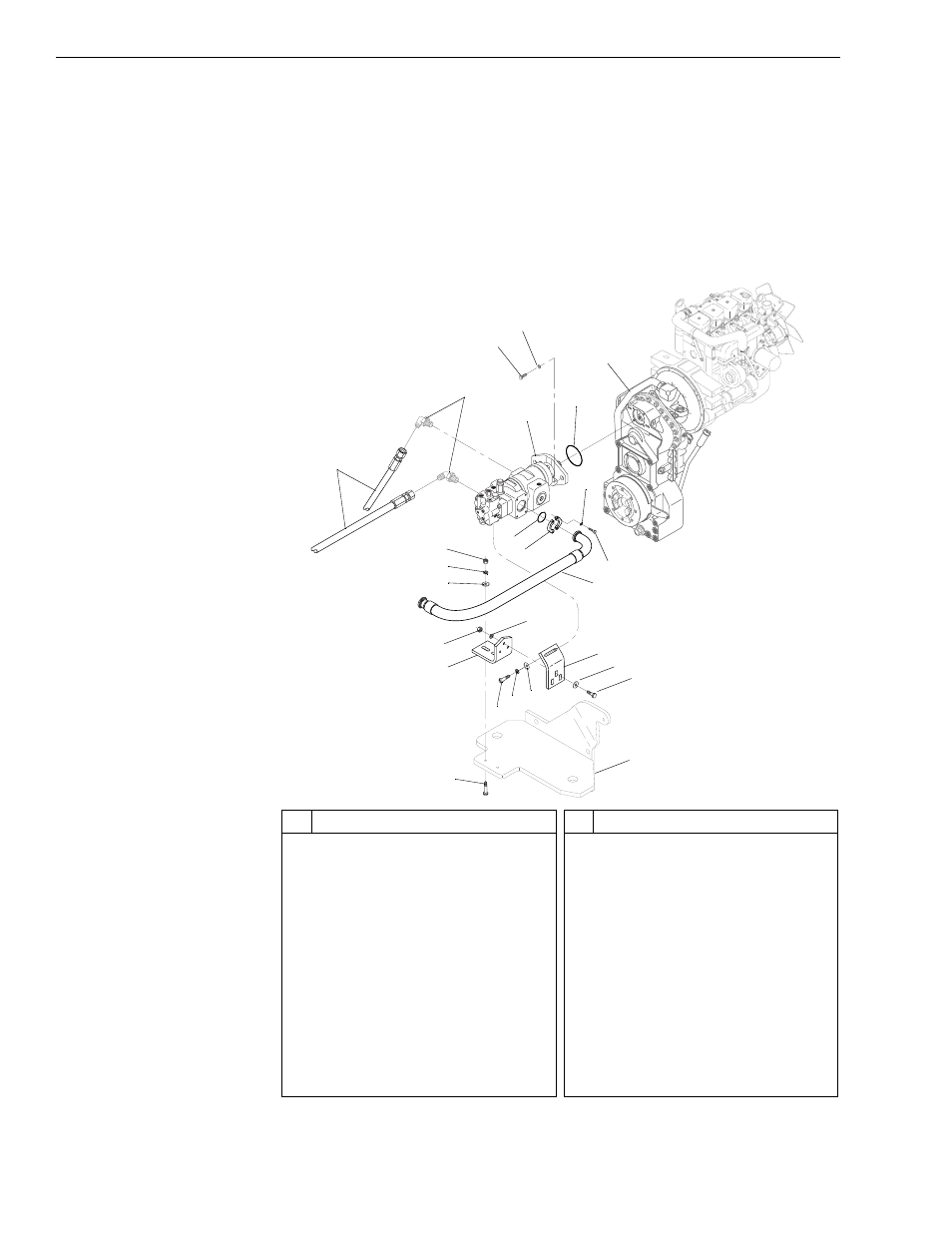
Fig. 5-26: Hydraulic Pump Installation – Mid-Inlet Hydraulics
#
Description
1
Hydraulic Hose
2
Elbow
3
Capscrew
4
Lockwasher
5
Hydraulic Pump
6
O-Ring
7
Transmission
8
O-ring
9
Flange Half
10 Lockwasher
11 Capscrew
12 Hydraulic Suction Hose
13 Nut
#
Description
14 Lockwasher
15 Flatwasher
16 Nut
17 Lockwasher
18 Lower Pump Support Bracket
19 Capscrew
20 Lockwasher
21 Flatwasher
22 Upper Pump Support Bracket
23 Flatwasher
24 Capscrew
25 Park Brake Cylinder Mount
26 Capscrew
K
1118
1
2
5
6
10
11
12
22
23
24
26
13
14
15
8
9
17
16
18
19 20
21
25
7
3
4