Disassembly – Lull 6K Service Manual User Manual
Page 255
Boom and Transfer
Service Manual — Models 644B, 6K, 844C, 8K, 1044C, 10K
6-5
Disassembly
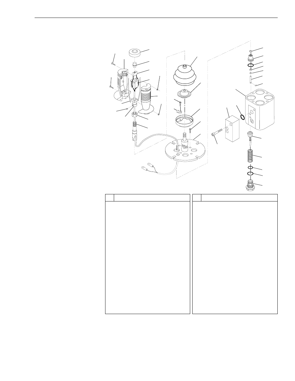
Joystick
Fig. 6-4: Joystick Components
(Ref. Fig. 6-4) The following steps are required to disassemble and repair
the joystick.
2
#
Description
1
Socket Head Capscrew
2
Socket Head Capscrew
3
Half Handle
4
Cap
5
Push Button
6
Switch
7
Guide
8
Hex Nut
9
Hex Nut
10 Seal
11 Setscrew
12 Lever Joint
13 Retaining Nut
14 Stem
15 Clip
16 Socket Head Capscrew
17 Boot
18 Cam
#
Description
19 Retainer
20 Flange
21 Socket Head Capscrew
22 Manifold
23 O-ring
24 Body
25 Wiper
26 Guide
27 O-ring
28 Seal
29 Spreader
30 Plunger
31 240
32 Spool
33 Spring
34 O-ring
35 O-ring
36 Ported Guide
J
1121
3
1
4
5
6
7
8
10
11
13
17
18
19
16
20
21
36
35
34
22 23
33
32
31
30
29
27
26
25
16
28
9
3
12
24
15
14
This manual is related to the following products: