Lull 6K Service Manual User Manual
Page 378
Boom and Transfer
6-128
Service Manual — Models 644B, 6K, 844C, 8K, 1044C, 10K
23. (Ref. Fig. 6-135) Install the auxiliary and carriage tilt hydraulic tubes
(Items 2 and 3) on the swivel elbows (Item 1) in the outer boom. Torque
the auxiliary tube swivel nuts to 50–58 ft-lbs and the carriage tilt tube
swivel nuts to 79–88 ft-lbs. Secure the hydraulic tubes to the boom
section with cushion clamps.
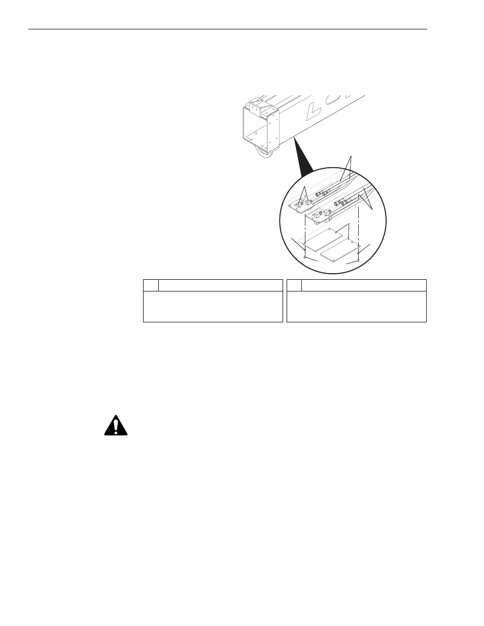
Fig. 6-136: Hose Installation, Outer Boom
24. (Ref. Fig. 6-136) Install the auxiliary and carriage tilt hydraulic hose
(Items 2 and 3) to the bulkhead elbows (Item 1) in the outer boom
section. Torque the auxiliary hose swivel nuts to 50–58 ft-lbs and the
carriage tilt hose swivel nuts to 79–88 ft-lbs.
25. Attach slings/chains to the outer boom section and the crane.
CAUTION: Make sure slings and chains are secure and a crane is
supporting the weight of the boom.
26. Position the outer boom section over the transfer carriage/boom cradle.
Carefully lower the outer boom and align the boom pivot boss with the
matching bosses in the transfer carriage/boom cradle.
J
109
2
#
Description
1
Bulkhead Elbows
2
Auxiliary Hydraulic Hoses
3
Carriage Tilt Hydraulic Hoses
#
Description
4
Access Cover
5
Lockwasher
6
Capscrew
2
5
1
4
5
6
6
3