Lull 6K Service Manual User Manual
Page 347
Boom and Transfer
Service Manual — Models 644B, 6K, 844C, 8K, 1044C, 10K
6-97
12. (Ref. Fig. 6-99) Install/remove shim(s) under the indicated pads to
obtain specified clearances.
13. Extend the boom and lubricate as per previous instructions.
14. Check the boom extension and retraction for binding against slide
pads.
Inspection Procedures
3-Section Boom
These procedures are intended to determine if localized deformation has
occurred on the inner and middle boom sections.
1. Extend the boom and lower the forks to the ground.
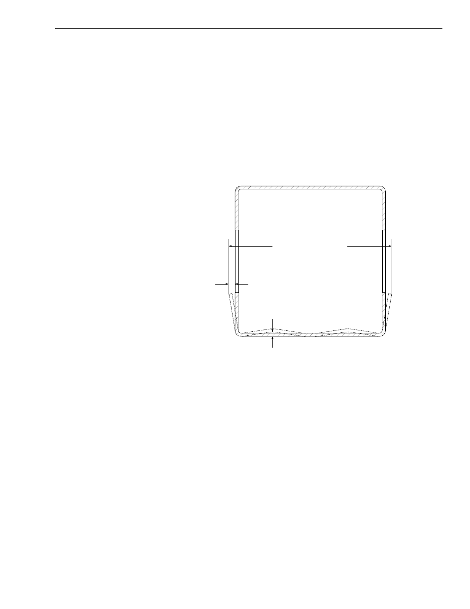
Fig. 6-100: Inner Boom Cross-Section at Window
2. (Ref. Fig. 6-100) Place a straight edge against the bottom surface of
the inner boom section. Measure the distance from the straight edge to
the bottom surface of the boom tube. This distance should not exceed
1/4" (0.25"). The maximum deflection will be found just in front of the
middle boom section.
3. (Ref. Fig. 6-100) The side walls may also deflect outward at the
window areas. Take this measurement across the inner boom tube,
through the windows. Maximum allowable deflection is 3/16" (0.19) per
side. The maximum allowable inner boom tube width is 12-3/8"
(12.38"), measured through the windows.
1/4" (0.25") Max.
3/16" (0.19")
J1085
12 3/8" (12.38") Max.