Oscillation control block, Description – Lull 6K Service Manual User Manual
Page 533
Frame Tilt and Oscillation
Service Manual — Models 644B, 6K, 844C, 8K, 1044C, 10K
7-31
Oscillation Control Block
Description
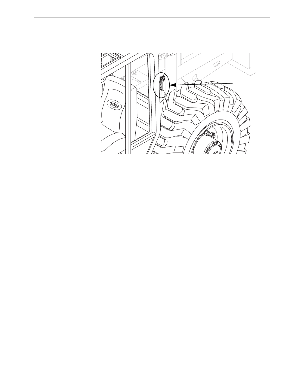
Fig. 7-20: Oscillation Control Block
(Ref. Fig. 7-20) The oscillation control block assembly controls the function
of the rear oscillation lock cylinder.
When the oscillation lock system is in UNLOCK mode, the control block
allows hydraulic fluid to freely pass into and out of the cylinder.
When the oscillation lock system is in LOCK mode, the control block traps
hydraulic fluid in both the rod-end and base-end of the cylinder. This
hydraulic lock in the cylinder prevents the frame from rotating on the rear
axle.
(See Section 4, “Reference Diagrams” for more information.)
Hydraulic ports on the block:
SYS = System pressure from Pump 1 (front pump section). This fluid
is routed to the cylinder.
T = Tank port. Fluid from this port is routed back to the hydraulic
reservoir.
PIL = Pilot pressure port. This fluid actuates the pilot pistons, allow-
ing free flow of fluid to/from the rear oscillation lock cylinder.
The major components of the oscillation control block assembly are:
1. Pressure reducing valve.
2. Solenoid valve (V1).
3. Two (2) check valves. These valves are labeled 3.1 and 3.2 on the
block body.
4. Two (2) pilot pistons.
0
80
6 0
4 0
2 0
- 2 0
G
1026
Rear Oscillation
Lock Control Block