Removal – Lull 6K Service Manual User Manual
Page 597
Brakes
Service Manual — Models 644B, 6K, 844C, 8K, 1044C, 10K
9-23
Removal
Accumulator
Models with Control Manifold Hydraulics
6K-37 (S/N 101–317)
6K-42 (S/N 101–119)
8K-42 (S/N 101–220)
10K-42 (S/N 101–106)
10K-54 (S/N 101–103)
644B-37 (S/N 101–590, 592–666)
644B-42 (S/N 101–207)
844C42 (S/N 101–521)
1044C-42 (S/N 101–116)
1044C-54 (S/N 101–154)
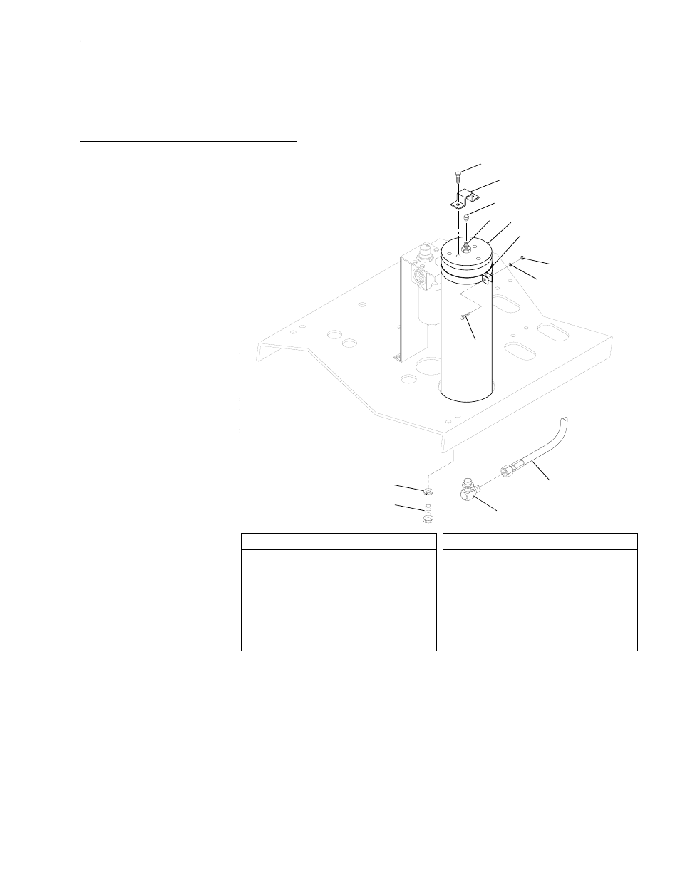
Fig. 9-14: Accumulator Installation – Models with Control Manifold
Hydraulics
The following procedure refers to Fig. 9-14.
1. Follow preparation procedures as outlined in Section 3 and in
Section 5 of this manual.
2. With the engine off, install a brake pressure diagnostic port test gauge
to the hose into the brake diagnostic port. This test gauge kit sold by
JLG includes a 3-foot long hose making it possible to read the gauge
from the operator cab.
#
Description
1
Capscrew
2
Gas Valve Guard
3
Gas Valve Cap
4
Gas Valve
5
Accumulator
6
Mounting Bracket
7
Hex Nut
#
Description
8
Lockwasher
9
Capscrew
10 Hydraulic Hose to AC Port
on Control Manifold
11 Elbow
12 Lockwasher
13 Hex Capscrew
2
K1
1
1
5
3
8
9
1
11
10
7
6
5
4
13
12