Service brake pedal and valve, Adjustment – Lull 6K Service Manual User Manual
Page 580
Brakes
9-6
Service Manual — Models 644B, 6K, 844C, 8K, 1044C, 10K
Service Brake Pedal and Valve
Adjustment
Service Brake Valve -
Models with Control
Manifold Hydraulics
6K-37 (S/N 101–317)
6K-42 (S/N 101–119)
8K-42 (S/N 101–220)
10K-42 (S/N 101–106)
10K-54 (S/N 101–103)
644B-37 (S/N 101–590, 592–666)
644B-42 (S/N 101–207)
844C-42 (S/N 101–521)
1044C-42 (S/N 101–116)
1044C-54 (S/N 101–154)
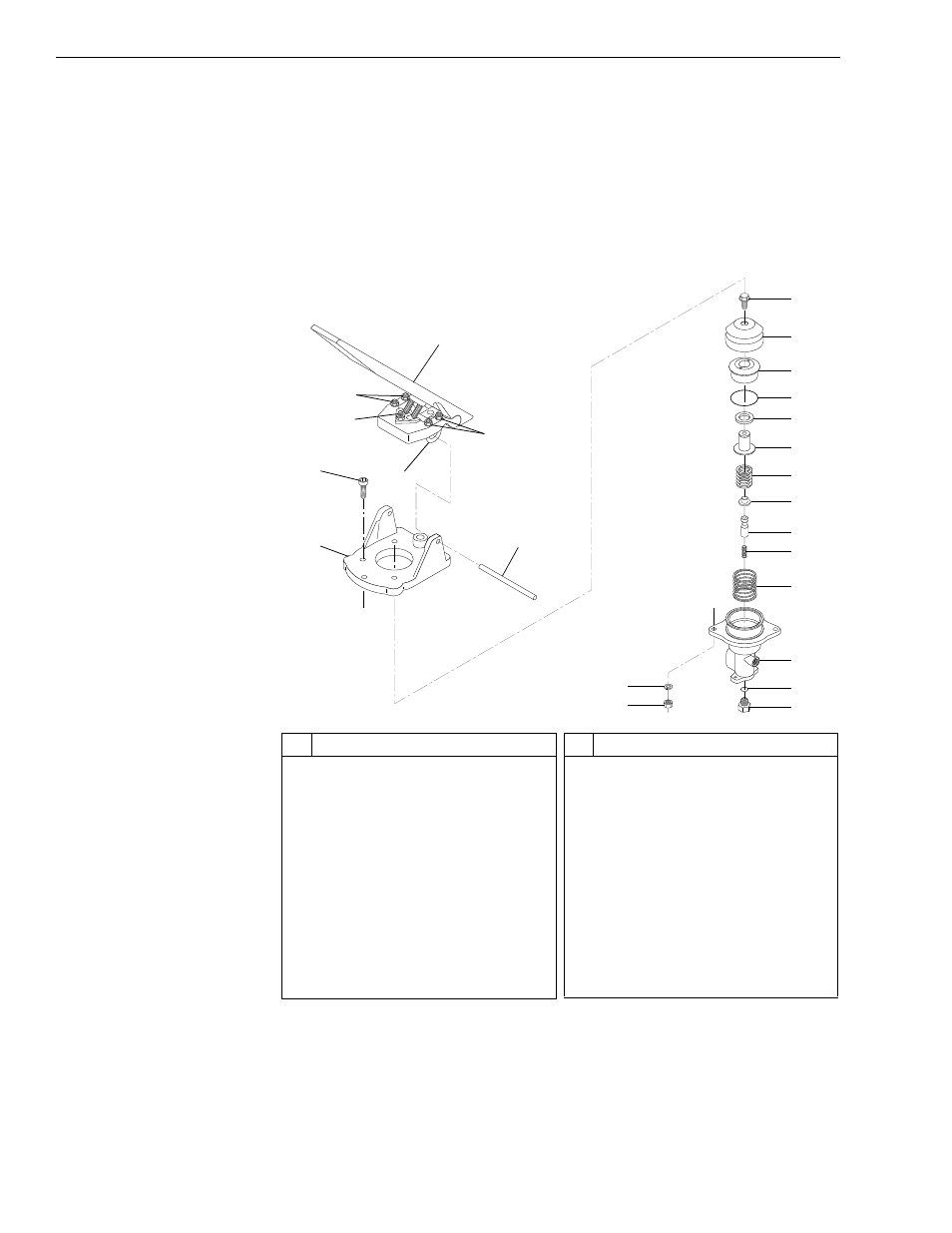
Fig. 9-5: Service Brake Valve Adjustment - Models with Control Manifold
Hydraulics
(Ref. Fig. 9-5) The following procedure is for checking and adjusting the
brake valve pressure for models with control manifold hydraulics.
#
Description
1
Brake Pedal
2
Hex Nut
3
U-Clamp
4
Deadband Setscrew
5
Socket Head Capscrew
6
Actuator Base
7
Pedal Mounting Pin
8
Flange Head Capscrew
9
Rubber Boot
10 Piston Guide
11 O-Ring
12 Seal
#
Description
13 Piston
14 Regulator Spring
15 Spring Seat
16 Spool
17 Spool Return Spring
18 Piston Return Spring
19 Body
20 O-Ring
21 Port Adapter
22 Lockwasher
23 Hex Jam Nut
0
8
-9
001
1
2
2
5
6
7
9
8
11
10
12
13
14
15
16
17
18
19
20
21
22
23
3
4