Lull 6K Service Manual User Manual
Page 368
Boom and Transfer
6-118
Service Manual — Models 644B, 6K, 844C, 8K, 1044C, 10K
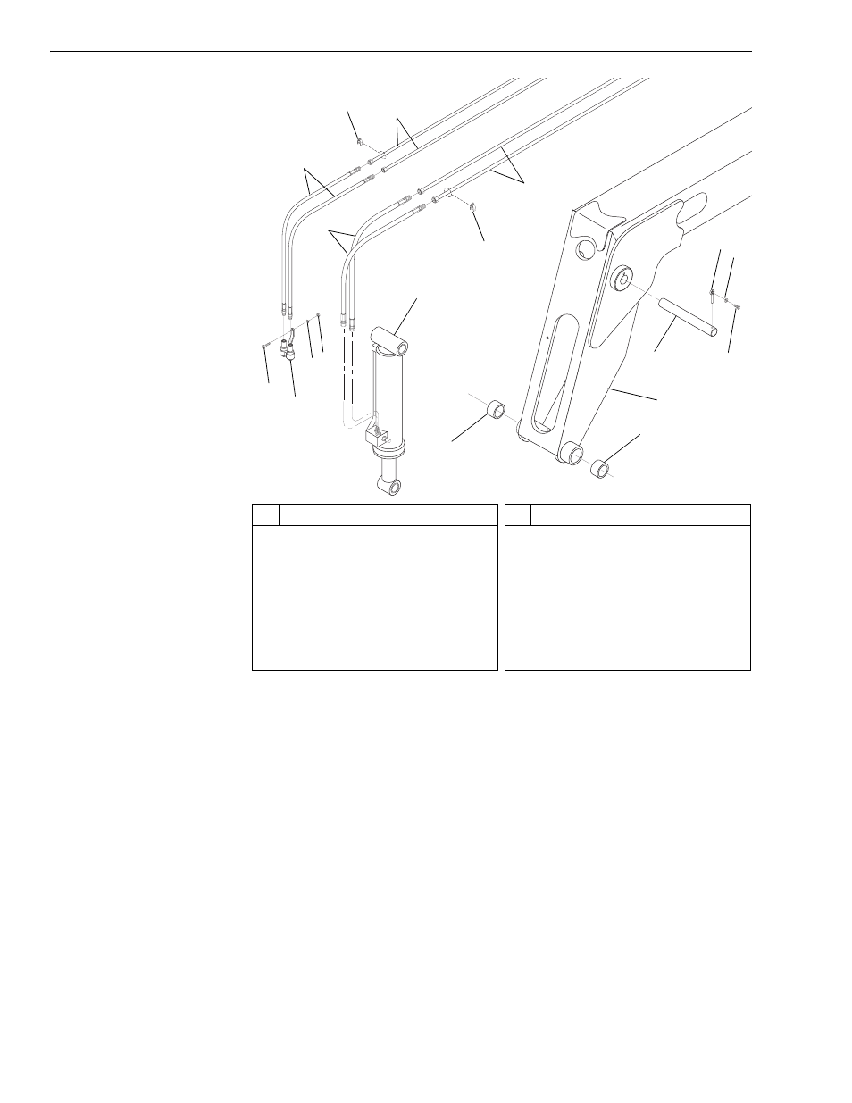
Fig. 6-125: Front Carriage Tilt Cylinder
44. (Ref. Fig. 6-125) Remove the nut (Item 9), lockwasher (Item 8), and
capscrew (Item 6) securing the quick disconnect coupler(s) (Item 7) to
the inner boom section.
45. (Ref. Fig. 6-125) Tag and remove the carriage tilt hydraulic hoses
(Item 4) from the connectors on the front carriage tilt cylinder (Item 10).
46. (Ref. Fig. 6-125) Tag and remove the auxiliary hydraulic hoses (Item 1)
from the quick disconnect coupler(s) (Item 7).
47. (Ref. Fig. 6-125) Cap hoses, tubes, and the connectors on the front
carriage tilt cylinder.
48. (Ref. Fig. 6-125) Loosen and remove the cushion clamps (Item 2)
securing the hydraulic tubes (Items 3 and 5) in the channels located
inside the inner boom section.
49. (Ref. Fig. 6-125) Remove all tubes and hoses from the inner boom
section.
J
1284
#
Description
1
Auxiliary Hydraulic Hoses
2
Cushion Clamp
3
Auxiliary Hydraulic Tubes
4
Carriage Tilt Hydraulic Hoses
5
Carriage Tilt Hydraulic Tubes
6
Capscrew
7
Quick Disconnect Coupler
8
Lockwasher
#
Description
9
Nut
10 Front Carriage Tilt Cylinder
11 Base End Pin
12 Lock Pin
13 Lockwasher
14 Capscrew
15 Inner Boom Section
16 Quick Attach Pivot Boom Bushing
1
3
9
7
6
8
2
4
5
2
10
11
12
13
14
16
16
15