Description – Lull 6K Service Manual User Manual
Page 278
Boom and Transfer
6-28
Service Manual — Models 644B, 6K, 844C, 8K, 1044C, 10K
644B-37 (S/N 101–434), 644B-42 (S/N 101–130),
6K-37 (S/N 101–229), 6K-42 (S/N 101–109),
844C-42 (S/N 101–319), and 8K-42 (S/N 101–180)
745 ft-lbs.
644B-37 (S/N 435–), 644B-42 (S/N 131–),
6K-37 (S/N 230–), 6K-42 (S/N 110–),
844C-42 (S/N 320–), and 8K-42 (S/N 181–)
1508 ft-lbs.
1044C -42 (S/N 101–), 1044C-54 (S/N 101–),
10K-42 (S/N 101–), and 10K-54 (S/N 101–)
550 ft-lbs.
16. Lubricate new seal and wear rings with hydraulic oil and install on
piston.
17. Coat inside of cylinder barrel (Item 2) with hydraulic oil. To avoid
damaging seals during assembly, carefully insert cylinder rod
assembly into cylinder barrel.
18. Install cylinder rod assembly in cylinder barrel. Install a spanner
wrench in two (2) holes of rod bearing head and tighten until it is snug
against the cylinder barrel.
19. Install two (2) elbows (Item 1) on cylinder manifold. Torque connectors
to 40–44 ft-lbs.
20. Lubricate grease fittings with EP lithium based grease.
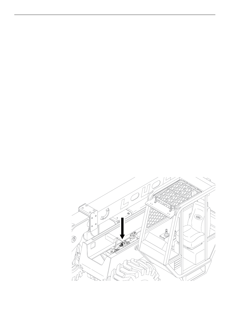
Boom Hydraulic Control Valve (Control Manifold System)
Description
644B-37 (S/N 101–590, 592–666)
644B-42 (S/N 101–207)
6K-37 (S/N 101–317)
6K-42 (S/N 101–119)
844C-42 (S/N 101–621)
8K-42 (S/N 101–220)
1044C-42 (S/N 101–116)
1044C-54 (S/N 101–154)
10K-42 (S/N 101–106)
10K-54 (S/N 101–103)
Fig. 6-17: Boom Hydraulic Control Valve
0
80
60
40
20
-20
K
1
106