Obtaining hardware information, Displaying fru information, Figure 10 fru properties dialog box – HP StorageWorks 2.32 Edge Switch User Manual
Page 49: 10 fru properties dialog box
Edge Switch Element Manager user guide
49
• Power indicator—The green indicator (PWR) simulates the power LED on the actual
switch. When the indicator is illuminated, the switch is connected to facility AC power and is
operational. The indicator will be on if either switch power supply is operating.
• System error indicator—The amber system error light indicator (ERR) simulates the
system error light on the actual switch. When this indicator is illuminated, an event has
occurred requiring immediate attention, such as a system, power supply/fan, or port failure.
View details of system errors by selecting Logs > Event Log on the Element Manager menu
bar. The indicator in the Hardware view and the LED on the actual unit remains illuminated
until you clear the event by right-clicking on the front view away from a hardware component
and clicking Clear System Error Light.
• Unit beaconing indicator— The amber system error indicator blinks if unit beaconing is
enabled. Enable and disable unit beaconing by right-clicking on the front view away from a
hardware component and clicking Enable Unit Beaconing. You can only enable
beaconing if there are no system errors (the system error indicator is off).
•
Power Supply Status 7—Each AC power connector indicates the location of an internal
power supply. An amber, service-required LED indicator is located in the upper left corner of
each AC power connector. The indicator is illuminated if the power supply has failed and
requires service. The indicator is off if the power supply is active.
When a blinking red and yellow diamond ( ) is displayed on a power connector, the internal
power supply for that connector has failed. Note that the switch still operates if one power
supply fails; however, you should replace the power supply as soon as possible to retain
redundancy.
Obtaining hardware information
The Element Manager enables you to display FRU information, port properties, and switch
properties using the various dialog boxes available on the Hardware view.
Displaying FRU information
Use one of the following methods to display the FRU Properties dialog box:
•
Double-click a FRU, such as a power supply module illustrated in the Hardware view.
•
Click a FRU in the Hardware view, then select Product > FRU > FRU Properties.
•
Double-click a row in the FRU List view.
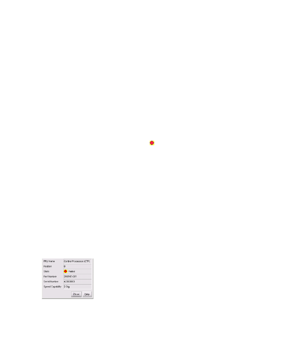
The FRU Properties dialog box displays the FRU name, slot position relative to identical FRUs
installed in the chassis, active or failed state, part number, serial number, and speed capacity.
Figure 10
FRU Properties dialog box