IAI America MSCON User Manual
Page 94
3.4 Fieldbus
Type
Address Map
86
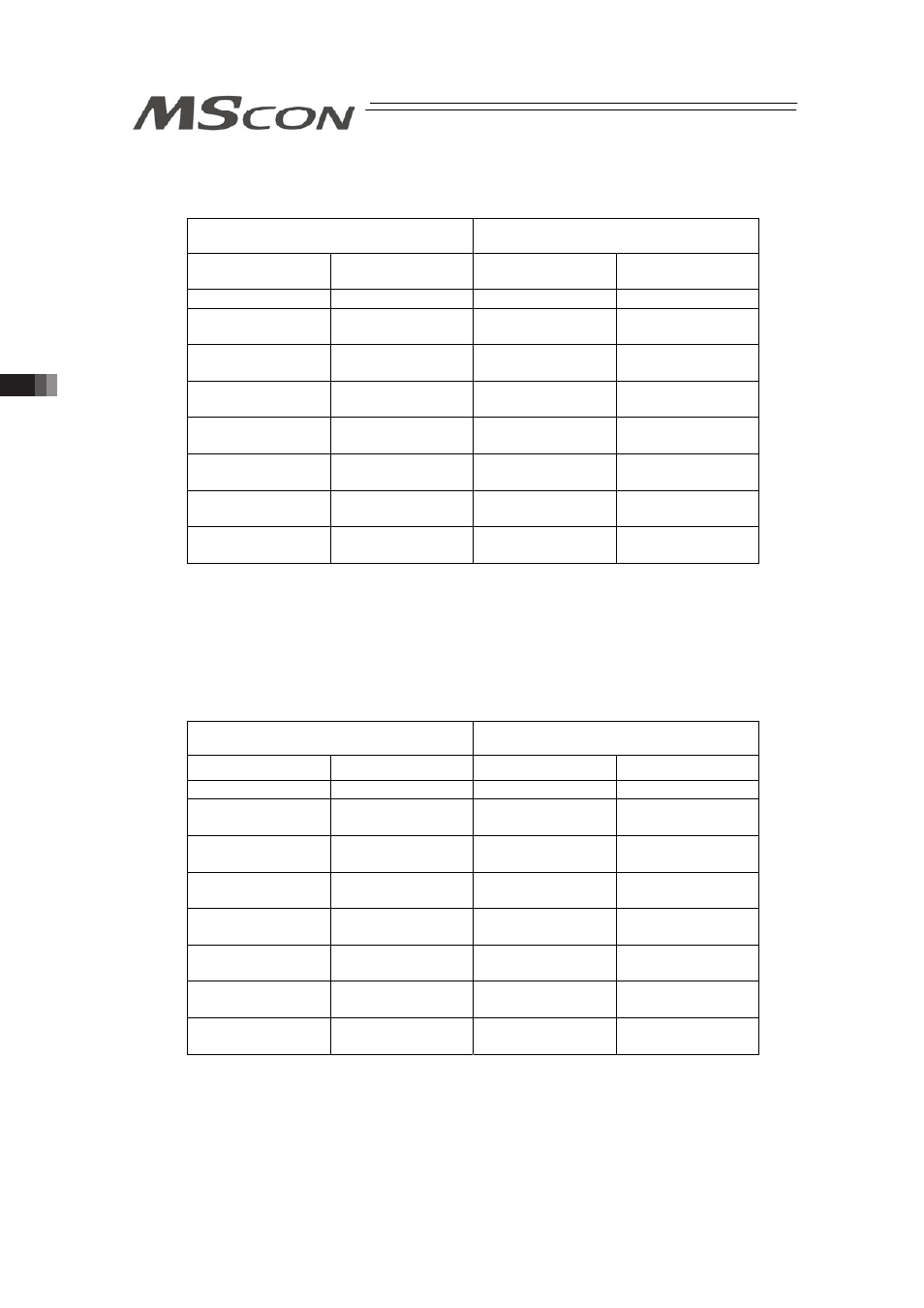
3) PROFIBUS-DP, EtherNet/IP, EtherCAT
(MECHATROLINK is not applicable for this mode)
(n is the top node address for each PLC input and output between MSCON and PLC)
PLCĺMSCON
MSCONĺPLC
Node address
(Byte Address)
Contents
Node address
(Byte Address)
Contents
n to n+3
Gateway Control
n to n+3
Gateway Status
n+4 to n+15
Demand
Command
n+4 to n+15
Response
Command
n+16 to n+19
Axis No.0 Control
Information
n+16 to n+19
Axis No.0 Status
Information
n+20 to n+23
Axis No.1 Control
Information
n+20 to n+23
Axis No.1 Status
Information
n+24 to n+27
Axis No.2 Control
Information
n+24 to n+27
Axis No.2 Status
Information
n+28 to n+31
Axis No.3 Control
Information
n+28 to n+31
Axis No.3 Status
Information
n+32 to n+35
Axis No.4 Control
Information
n+32 to n+35
Axis No.4 Status
Information
n+36 to n+39
Axis No.5 Control
Information
n+36 to n+39
Axis No.5 Status
Information
[3] Address Map for Positioner 3 Mode
Shown below is the address map for each Field network when six axes of MSCON are
operated in Positioner 3 Mode.
1) DeviceNet, CompoNet
(n is the top channel number for each PLC input and output between MSCON and PLC)
PLCĺMSCON
MSCONĺPLC
CH No.
Contents
CH No.
Contents
n to n+1
Gateway Control
n to n+1
Gateway Status
n+2 to n+7
Demand
Command
n+2 to n+7
Response
Command
n+8
Axis No.0 Control
Information
n+8
Axis No.0 Status
Information
n+9
Axis No.1 Control
Information
n+9
Axis No.1 Status
Information
n+10
Axis No.2 Control
Information
n+10
Axis No.2 Status
Information
n+11
Axis No.3 Control
Information
n+11
Axis No.3 Status
Information
n+12
Axis No.4 Control
Information
n+12
Axis No.4 Status
Information
n+13
Axis No.5 Control
Information
n+13
Axis No.5 Status
Information