IAI America MSCON User Manual
Page 177
3.8 C
ontrol and functions of Input and output signals of Remote I/O Mode
169
3.8 Control and functions of Input and output signals of Remote I/O Mode
3.8.1 Operation Supportive Signal = Patterns 0 to 2, 4 and 5 in common
[1] Emergency stop status (EMGS)
Output
PIO Signal
*EMGS
In common for
all PIO patterns
{
{
: Available, u: Unavailable
1) The emergency stop status EMGS is turned ON when in normal condition and turned OFF
when it opens between EMG+ and EMG- (emergency stop condition or disconnected) for
“Emergency Stop Circuit”.
2) The signal turns on once the emergency stop condition is cancelled and it closes between
EMG+ and EMG-.
Have an appropriate safety treatment such as interlock with this signal for the host controller
(PLC, etc.).
(Note) It is not an emergency stop output due to an alarm generation of the controller.
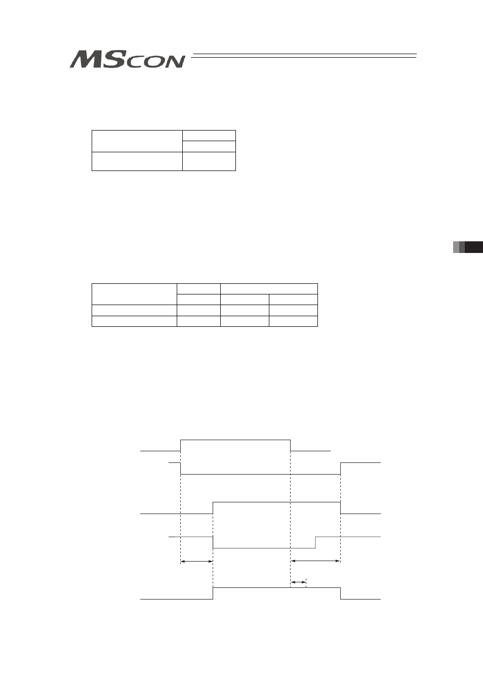
[2] Servo ON (SON, SV, PEND)
Input
Output
PIO Signal
SON
SV
PEND
Other than pattern 5
{
{
{
Pattern 5
{
{
u
{
: Available, u: Unavailable
1) Servo ON signal SON is the input signal making the servo motor of the actuator operable.
2) If the servo-on is performed to enable operation, the SV output signal is turned ON.
The positioning complete signal PEND turns ON at the same time.
3) With the power being supplied, then controller cannot be operated while the SV signal
remains OFF. If the SON signal is turned OFF under operation of the actuator, the actuator is
decelerated and stopped with the emergency stop torque, the servo is turned OFF and the
motor gets into the free-run condition.
The brake (option) is excitation release type. Therefore, the brake gets released when
excitation is ON and the brake works (locks) when excitation is OFF.
Dynamic Brake
Brake Excitation
Lock
Release
It may differ due to operation condition
and load condition.
SON
SV
20ms
100ms
PEND
(Note)
Lock
Release
(MSCON → PLC)
(PLC → MSCON)
(MSCON → PLC)
(Note 1)
Note1: PEND would not turn ON in the pause condition.