1) controller ready (crdy) plc input signal, 2) emergency stop (emgs) plc input signal, 3) alarm (alm) plc input signal – IAI America MSCON User Manual
Page 155: 4) reset (res) plc output signal
3.7
Control and functions of Input and output signals of Modes other than Remote I/O Mode
Power Supply and Cutof
f
147
3.7 Control and functions of Input and output signals of Modes other than
Remote I/O Mode
Input and output signals are prepared for each axis number.
The applicable bit is “1” when the signal is ON and “0” when it is OFF.
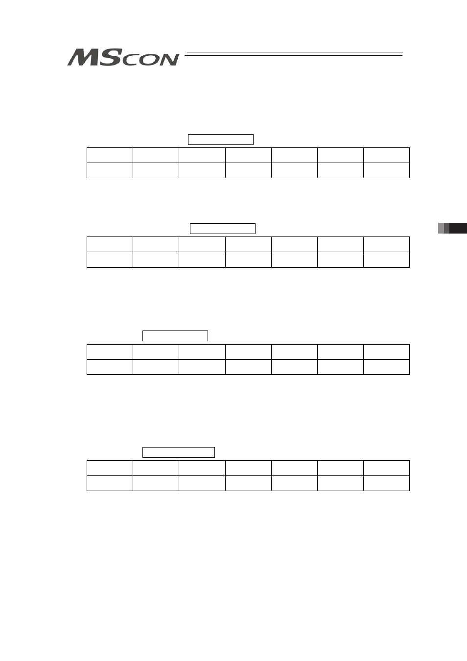
(1) Controller ready (CRDY) PLC Input Signal
Operation
Mode
Positioner 1
Simple Direct
Direct numeric
specification
Direct numeric
specification 2
Positioner 2
Positioner 3
{
: Equipped
× : Not equipped
{
{
{
{
{
×
Regardless of the alarm or servo conditions, when the MSCON initialization is completed
normally after the power injection and the controller can control the system, it is turned ON.
Even in the alarm condition, when the MSCON can control the system, it is turned ON.
(2) Emergency stop (EMGS) PLC Input Signal
Operation
Mode
Positioner 1
Simple Direct
Direct numeric
specification
Direct numeric
specification 2
Positioner 2
Positioner 3
{
: Equipped
× : Not equipped
{
{
{
{
{
{
When the controller is stopped in an emergency (motor driving power is cut off), it is turned ON.
When the emergency stop status is cleared, it is turned OFF.
Also, ALM* in the driver status LEDs flashes.
Have an appropriate safety treatment such as interlock with this signal for the host controller.
(Note) It is not an emergency stop output due to an alarm generation of the controller.
(3) Alarm (ALM) PLC Input Signal
Operation
Mode
Positioner 1
Simple Direct
Direct numeric
specification
Direct numeric
specification 2
Positioner 2
Positioner 3
{
: Equipped
× : Not equipped
{
{
{
{
{
{
This is a signal that is OFF in normal condition and turns ON when an alarm of operation
cancelled level
(Note 1)
or higher is generated. This signal turns OFF once the reset (RES) signal
is turned oON while an alarm of operation cancelled level is being generated. (In the case of
the alarm with the cold start level, re-injection of the power is required.)
Also, ALM* in the driver status LEDs flashes.
Note 1: Refer to 8.4 Alarm List for details of alarms.
(4) Reset (RES) PLC Output Signal
Operation
Mode
Positioner 1
Simple Direct
Direct numeric
specification
Direct numeric
specification 2
Positioner 2
Positioner 3
{
: Equipped
× : Not equipped
{
{
{
{
{
{
The reset signal RES possesses two functions, one is an alarm reset while an alarm is being
generated, and the other is to cancel the operation while in a pause.
1) Once this signal is turned ON while an alarm of operation cancelled level is being generated,
the alarm is cancelled. (In the case of the alarm with the cold start level, re-injection of the
power is required.) Confirm the cause of the alarm and remove it before conducting a reset
of the alarm. Having the alarm reset repeatedly without removing the cause of the alarm to
restart the operation may cause a critical malfunction such as motor burn-down.
2) When this signal is turned ON from OFF condition during the pause condition, the reminder
of the planned movement left can be cancelled and the remained operation can be deleted.