IAI America MSCON User Manual
Page 127
3.4 Fieldbus
Type
Address Map
119
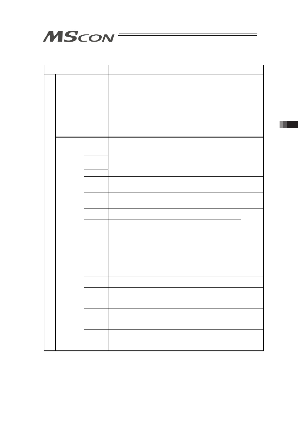
(3) I/O signal assignment
(ON = Applicable bit is “1”, OFF = Applicable bit is “0”)
Signal Type
Bit
Symbol
Contents
Details
Specified
Position
No.
16 bits
Data
PC1 to PC128
16-bit integer
Available range for Setting: 0 to 255
To operate, it is necessary to have the position
data that the operation conditions are already set
in advance with a teaching tool such as the PC
software.
In this register, indicate the position number the
data is input with a binary number.
Indicating a value out of the range or operating
with a position number with no setting conducted
will generate the alarm code 0A2 “Position Data
Error”.
3.7 (29)
b15
BKRL
Brake release
ON: Brake release, OFF: Brake activated
3.7 (17)
b14
b13
b12
b11
–
Unavailable
–
b10
MODE
Teaching mode command
(Invalid in Simple Direct Mode)
OFF: Standard mode, ONᾉTeaching mode
3.7 (15)
b9
PWRT
Position import command
(Invalid in Simple Direct Mode)
ON: Position Data Import
3.7 (16)
b8
JOG+
+Jog
ON: Movement against home position, OFF: Stop
b7
JOG-
-Jog
ON: Movement toward home position, OFF: Stop
3.7 (12)
b6
JVEL
Jog-speed/inch-distance switching
OFF : Use the setting values of Parameter No. 6
JOG Speed and No.48 Inching Distance in
MSCON
ON : Use the setting values of Parameter No. 7
JOG Speed 2 and No.49 Inching Distance
in MSCON
3.7 (13)
b5
JISL
Jog/inching switching
ON: Inching, OFF: Jog
3.7 (14)
b4
SON
Servo ON Command
ON: Servo ON, OFF: Servo OFF
3.7 (5)
b3
RES
Reset
A reset is performed when this signal turns ON.
3.7 (4)
b2
STP
Pause
ON: Pause, OFF: Pause Release
3.7 (10)
b1
HOME
Home return
Home-return command with this signal ON,
command carried on till complete even if the
signal is turned OFF on the way
3.7 (6)
P
LC
In
pu
t
Control
Signal
b0
CSTR
Positioning Start
Movement command executed with this signal
ON, command carried on till complete even if the
signal is turned OFF on the way
3.7 (7)