IAI America MSCON User Manual
Page 161
3.7
Control and functions of Input and output signals of Modes other than Remote I/O Mode
Power Supply and Cutof
f
153
Caution: When the servo-motor is turned OFF or stopped in an emergency while the
actuator is stopped at the target position, the PEND signal is turned OFF
temporarily.
Then, when the servo-motor is turned ON and the actuator is within the
positioning width, the PEND signal is turned ON again.
When the positioning is completed with the CSTR signal turned ON, the
PEND signal is not turned ON.
(8) Pause (STP) PLC Output Signal
Operation
Mode
Positioner 1
Simple Direct
Direct numeric
specification
Direct numeric
specification 2
Positioner 2
Positioner 3
{
: Equipped
× : Not equipped
{
{
{
{
{
{
When this signal is turned ON, the actuator movement is decelerated and stopped. When it is
turned OFF, the actuator movement is restarted.
The acceleration in the operation restart or the deceleration in stopping operation, is expressed
as the value for the acceleration/deceleration for the position No. set using the specified
position No. resister in the Position* Mode and Simplified Direct Value Mode, and as the value
set in the acceleration/deceleration register in the Derect indication mode.
(9) Zone 1 (ZONE1)
PLC Input Signal
Zone 2 (ZONE2)
PLC Input Signal
Position Zone (PZONE)
PLC Input Signal
Operation
Mode
Positioner 1
Simple Direct
Direct numeric
specification
Direct numeric
specification 2
Positioner 2
Positioner 3
{
: Equipped
× : Not equipped
{
{
U
(No PZONE)
U
(No PZONE)
{
U
(Only for
PZONE1)
This is a function enables to turn a signal on while the actuator is passing a certain position (in
the zone range) or during a stop, in which there are two types.
1) Zone signal (ZONE1, ZONE2)·· Turn the output on at a position set in the parameter.
2) Position zone signal (PZONE)·· Turn the output on at a position set in the position table.
The roles of a sensor, such as the judgment of complete position at pressing complete,
continuous operation range setting for the pitch feed or operation interlock of other devices in
the setting range, can be made available.
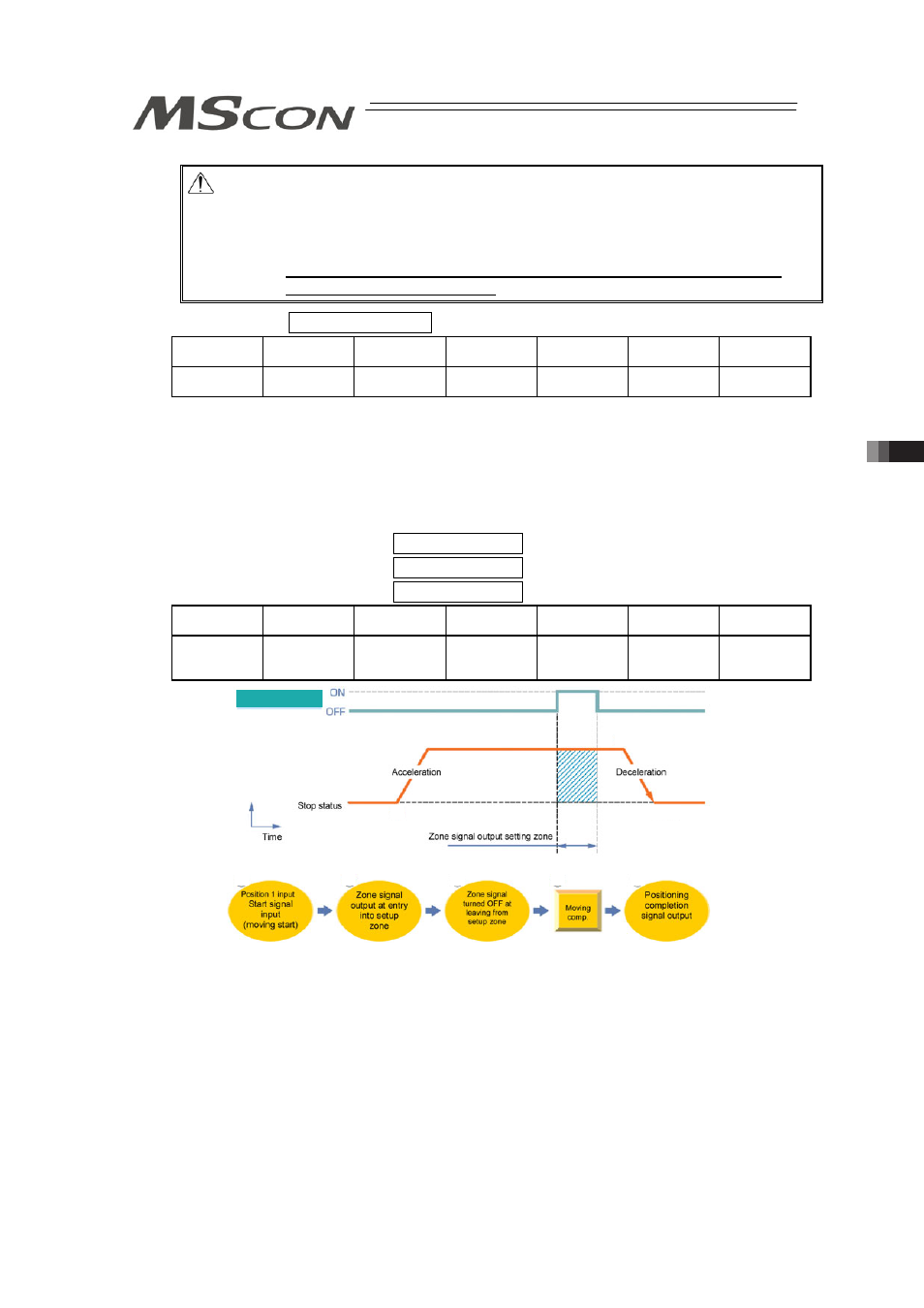
(1) Zone signal (ZONE1, ZONE2)
Set the zone range to the parameter.
1) ZONE1: Parameter No.1 (Zone boundary 1+), Parameter No.2 (Zone boundary 1-)
2) ZONE2: Parameter No.23 (Zone boundary 2+), Parameter No.24 (Zone boundary 2-)
The zone signal is kept effective also during the emergency stop unless the memory of the
origin is lost due to alarm.
Time
Velocity
Zone output signal
1)
2)
3)
4)
5)
1)
2)
3)
4) 5)