IAI America MSCON User Manual
Page 205
3.8 C
ontrol and functions of Input and output signals of Remote I/O Mode
197
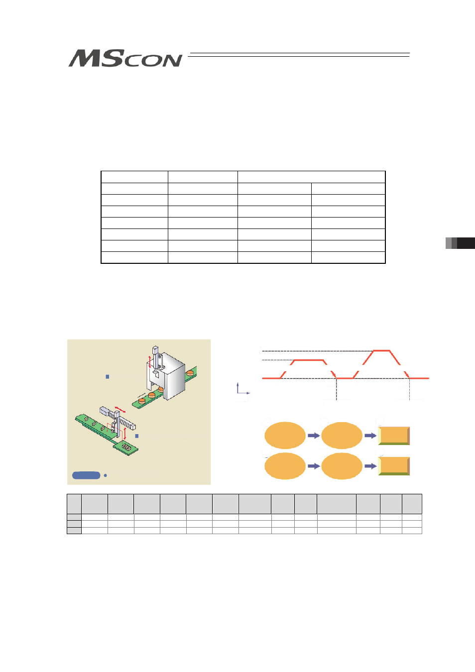
3.8.3 Direct Position Specification (Solenoid Valve Mode 1) = Operation of PIO
Pattern 4
The start signal is provided for every position number. Only turning ON the relevant input signal
according to the table shown below allows the operation based on the data in the target
position number to be performed. The operation mode is called the solenoid valve mode
because solenoid valves can directly drive air cylinders.
At the completion of positioning, every completed position number is output as well as the
positioning complete signal.
[1] Positioning [Basic] (ST1 to ST6, PE1 to PE6, PEND)
Position No.
Input
Output
0
ST0
PE0
PEND
1
ST1
PE1
PEND
2
ST2
PE2
PEND
3
ST3
PE3
PEND
4
ST4
PE4
PEND
5
ST5
PE5
PEND
6
ST6
PE6
PEND
[Caution] x Speed change is not allowed during movement.
x
If start signal ST* is issued without home return, the home return operation is
automatically done before the operation based on the data of the specified
position number. When this specification is not desired, interlock by home return
complete signal HEND is required.
Sample use
No.
Position
[mm]
Velocity
[mm/s]
Accele-
ration
[G]
Decele-
ration
[G]
Pressing
[%]
Thresh-
old
[%]
Positioning
width
[mm]
Zone+
[mm]
Zone-
[mm]
Acceleration/
Deceleration
mode
Incre-
mental
Gain
set
Stop
mode
0
0.00
100.00
0.20
0.20
0
0
0.10
0.00
0.00
0
0
0
0
1
70.00
100.00
0.20
0.20
0
0
0.10
0.00
0.00
0
0
0
0
2
150.00
200.00
0.20
0.20
0
0
0.10
0.00
0.00
0
0
0
0
Used for door
open/close
Used for pick & place unit
Work carriage, movement, etc.
Usage
Deceleration
Position 1
Acceleration
2
)
3
)
1
)
4
)
5)
Input start signal
to Position No.1
(Moving start)
Moving
comp.
Positioning
complete signal
of position 1
output
Acceleration
Deceleration
Position 2
6
)
2) 3)
1)
4)
5) 6)
200mm/sec
100mm/sec
Stop
status
Velocity
Time
Input start signal
to Position No.2
(Moving start)
Moving
comp.
Positioning
complete signal
of position 2
output