IAI America MSCON User Manual
Page 133
3.4 Fieldbus
Type
Address Map
125
(1) PLC Address Composition
(m is PLC input and output top word address for each axis number)
PLCĺMSCON (PLC Output)
MSCONĺPLC (PLC Input)
Port No.0 to 15
m
Port No.0 to 15
m
[Refer to Section 3.4.2 for the address maps for each Fieldbus.]
(2) Input and Output Signal Assignment for each Axis
The I/O signals for each axis consists of 1 word for each I/O bit register.
Ɣ The I/O bit register is controlled using the ON/OFF signal in units of bit.
(ON = Applicable bit is “1”, OFF = Applicable bit is “0”)
Ɣ The content of the signal for each bit changes depending what is selected in the PIO
patterns.
[Refer to next section I/O signal assignment]
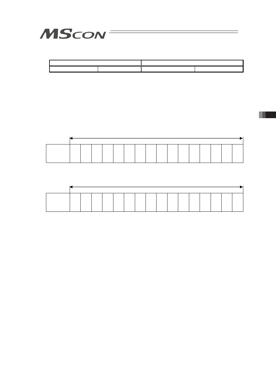
PLC Output (m is PLC input and output top word address for each axis number)
Address m
b15 b14 b13 b12 b11 b10
b9
b8
b7
b6
b5
b4
b3
b2
b1
b0
Controller
Input port
No.
15
14
13
12
11
10
9
8
7
6
5
4
3
2
1
0
PLC Input (m is PLC input and output top word address for each axis number)
䎃
Address m
F
E
D
C
B
A
9
8
7
6
5
4
3
2
1
0
Controller
Output Port
No.
15
14
13
12
11
10
9
8
7
6
5
4
3
2
1
0
䎃
1 word=16 bit
1 word=16 bit