IAI America MSCON User Manual
Page 91
3.4 Fieldbus
Type
Address Map
83
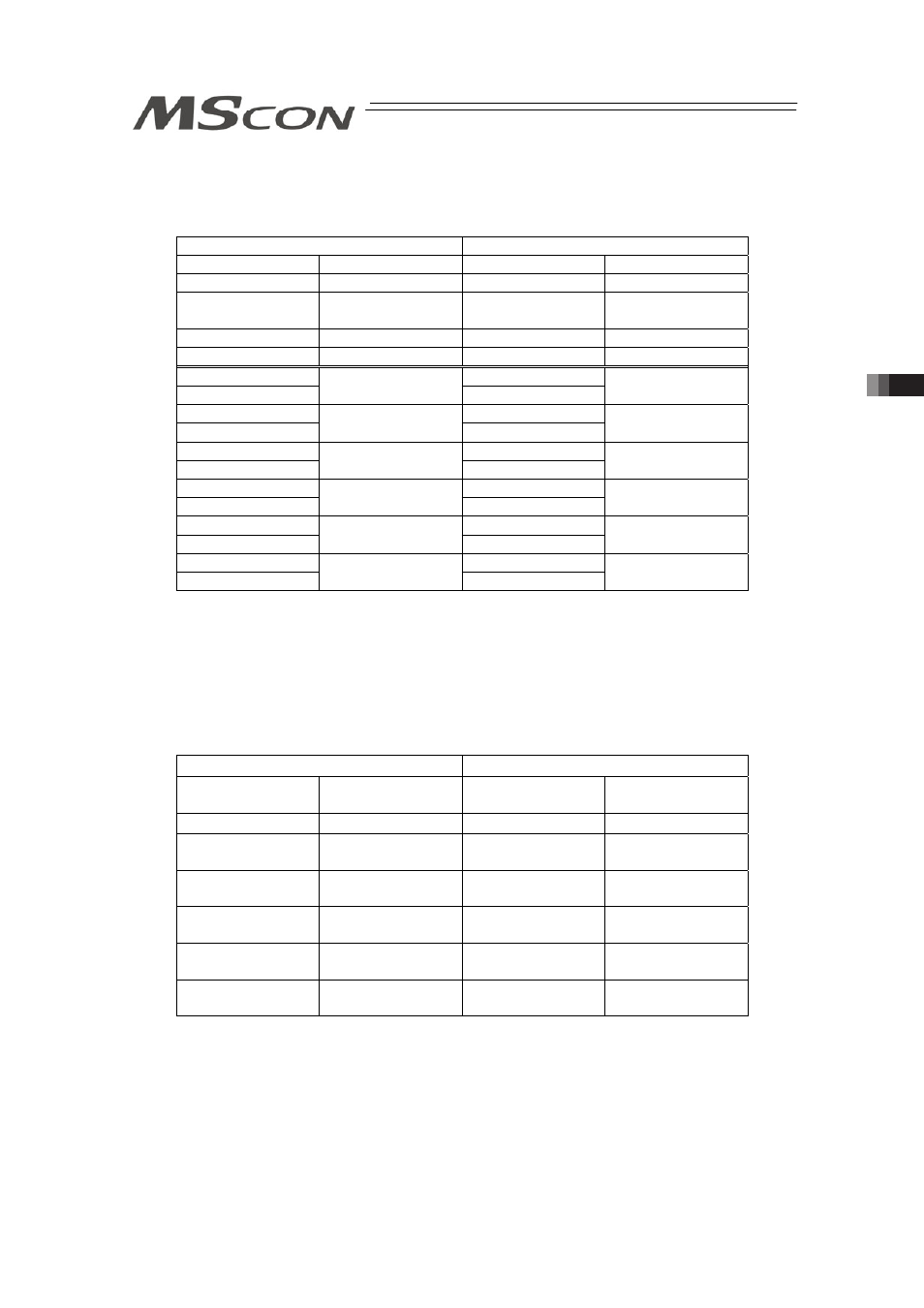
[Combination Example 3] When number of Simple Direct Mode axes is 0 and number of Direct
Indication Mode 6
(Extended Cyclic Setting/Number of Occupied Stations: 8 times/2
stations)
PLCĺMSCON
MSCONĺPLC
Address
Contents
Address
Contents
RY 000 to 01F
Gateway Control
RX 000 to 01F
Gateway Status
RY 020 to 06F
Demand
Command
RX 020 to 06F
Response
Command
RY 070 to 07F
Unavailable
RX 070 to 07F
Unavailable
RY 080 to 17F
Unavailable
RX 080 to 17F
Unavailable
RWw 00 to 03
RWr 00 to 03
RWw 04 to 07
Axis No.0 Control
Information
RWr 04 to 07
Axis No.0 Status
Information
RWw 08 to 0B
RWr 08 to 0B
RWw 0C to 0F
Axis No.1 Control
Information
RWr 0C to 0F
Axis No.1 Status
Information
RWw 10 to 13
RWr 10 to 13
RWw 14 to 17
Axis No.2 Control
Information
RWr 14 to 17
Axis No.2 Status
Information
RWw 18 to 1B
RWr 18 to 1B
RWw 1C to 1F
Axis No.3 Control
Information
RWr 1C to 1F
Axis No.3 Status
Information
RWw 20 to 23
RWr 20 to 23
RWw 24 to 27
Axis No.4 Control
Information
RWr 24 to 27
Axis No.4 Status
Information
RWw 28 to 2B
RWr 28 to 2B
RWw 2C to 2F
Axis No.5 Control
Information
RWr 2C to 2F
Axis No.5 Status
Information
3) PROFIBUS-DP, EtherNet/IP, EtherCAT
(MECHATROLINK is not applicable for this mode)
[Combination Example 1] When number of Simple Direct Mode axes is 4 and number of Direct
Indication Mode 0
(n is the top channel number for each PLC input and output between
MSCON and PLC)
PLCĺMSCON
MSCONĺPLC
Node address
(Byte Address)
Contents
Node address
(Byte Address)
Contents
n to n+3
Gateway Control
n to n+3
Gateway Status
n+4 to n+15
Demand
Command
n+4 to n+15
Response
Command
n+16 to n+23
Axis No.0 Control
Information
n+16 to n+23
Axis No.0 Status
Information
n+24 to n+31
Axis No.1 Control
Information
n+24 to n+31
Axis No.1 Status
Information
n+32 to n+39
Axis No.2 Control
Information
n+32 to n+39
Axis No.2 Status
Information
n+40 to n+47
Axis No.3 Control
Information
n+40 to n+47
Axis No.3 Status
Information