IAI America MSCON User Manual
Page 299
Chapter 8
Troubleshooting
291
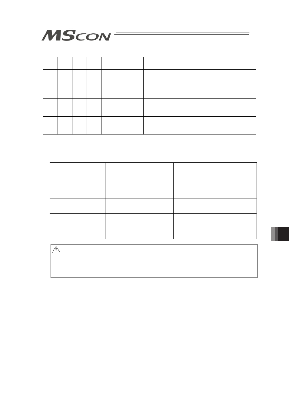
{
: ON z : OFF
*ALM ALM8
(PM8)
ALM4
(PM4)
ALM2
(PM2)
ALM1
(PM1) Binary Code
Description: Alarm code is shown in ( ).
z
{
{
z
{
13
Encoder send error (0E4)
Encoder Receipt Error (0E5)
Encoder count error (0E6)
Absolute Encoder Error Detection 2 (0EE)
Absolute Encoder Error Detection 3 (0EF)
z
{
{
{
z
14
CPU Error (0FA)
FPGA Error (0FB)
Logic Error (0FC)
z
{
{
{
{
15
Nonvolatile memory write verify error (0F5)
Nonvolatile memory write timeout (0F6)
Nonvolatile memory data destroyed (0F8)
(Note) *ALM Signal is an active low signal. It is ON when the power is applied to the controller, and
turns OFF when the signal is output.
[2] Alarm Level
The alarms are classified to 3 types of levels by the content of the error.
Alarm level
ALM lamp *ALM signal
Status when an
error occurred
Cancellation method
Message
OFF
No output
No stop
Alarm of maintenance output such as
excess of number of movement times or
of the teaching tool such as PC software
[Refer to Instruction Manual of each tool
for details.]
Operation
release
ON
Output
Servo OFF after
deceleration to
stop
Alarm reset by teaching tool
Cold start
ON
Output
Servo OFF after
deceleration to
stop
Software reset or power reconnection by
teaching tool.
Home return is required for any
actuators of other than absolute
specification.
Caution: Reset each alarm after identifying and removing the cause.
If the cause of the alarm cannot be removed or when the alarm cannot be reset
after removing the cause, please contact IAI.
If the same error occurs again after resetting the alarm, it means that the cause of
the alarm has not been removed.