According to sequence program creation – IAI America MSCON User Manual
Page 17
9
7. For the rotary actuator, it is necessary to pay attention to cable breakage due to
twisting and other factors.
Especially for the type with a through hole in the center of rotation, and when using it with
cables going through the hole, and also for the actuator with 360q rotation, special care is
required because there is no limit to the rotation in one direction.
8. Limitations on operation of rotary actuator in index mode
Rotary actuators of 360q specification can select the normal mode for finite rotations or the
index mode enabling multi-rotation control by using parameter No.79 “Rotational axis mode
selection”.
[Refer to Chapter 7 Parameter.]
The following limitations are applied to the index mode:
1) Index Mode cannot be selected in the absolute type controllers. It will issue Alarm Code
0A1 “Parameter Data Error”.
2) In the JOG operation by PC software, a teaching pendant or PIO Signal, the indicated
range in one time is from 0 to 360.00q and that makes one turn.
3) Pressing is unavailable. The pressing torque can only be set to 0.
4) Do not issue positioning command around 0q repeatedly during movement near 0°. Failure
to follow this may cause the actuator to rotate in the direction reverse to the specified
rotation direction or operate indefinitely.
5) Soft stroke limit is invalid in the index mode.
9. According to sequence program creation
Please note the following things when creating a sequence program.
When data transfer is necessary between two devices that have a different scan time from each
other, duration more than the longer scan time is required to certainly read the signal. (To have
the loading process on PLC side safely, it is recommended to set the timer to at least twice
longer than the long scanning time.)
䎃
䧎䎃
Operation Image䎃
䎃
䎃
䎃
䎃
䎃
䎃
䎃
䎃
䎃
䎃
䎃
䎃
䎃
䎃
䎃
䎃
䎃
䎃
䎃
䎃
䎃
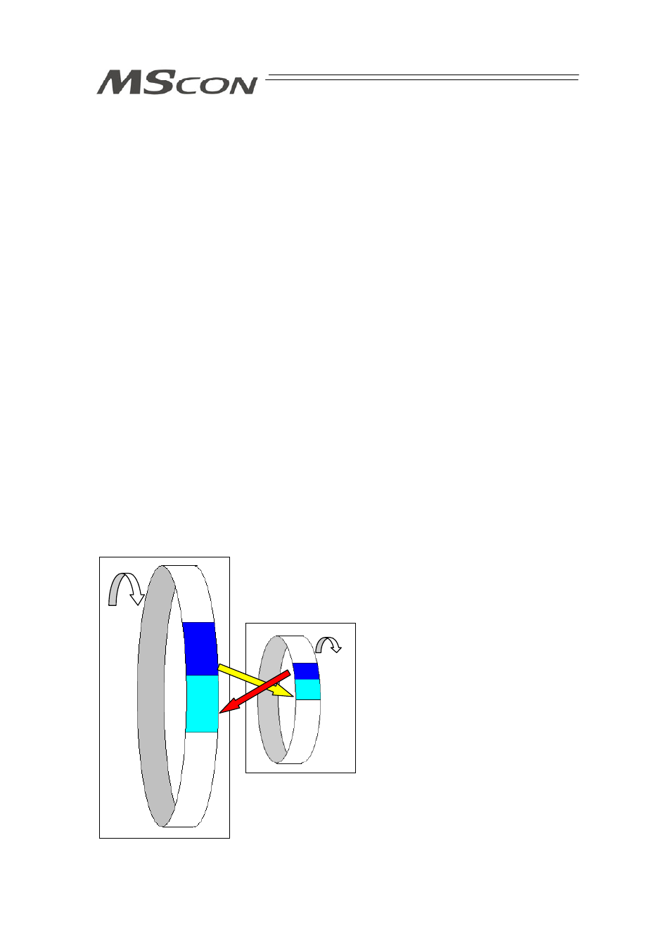
This controller
(scan time 1msec)
PLC (Programmable Logic Controller)
(example: scan time is 20msec)
Output
Process
Input
Process
As shown in the diagram, the input and output
timings of two devices that have different scan
time do not match, of course, when transferring
a signal.
There is no guarantee that PLC would read the
signal as soon as this controller signal turns
ON.
In such a case, make the setting to read the
signal after a certain time that is longer than the
longer scan time to ensure the reading process
to succeed on the PLC side.
It is the same in the case this controller side
reads the signal.
In such a case, it is recommended to ensure 2
to 4 times of the scan time for the timer setting
margin.
It is risky to have the setting below the scan
time since the timer is also processed in the
scan process.
In the diagram, PLC can only read the input
once in 20msec even though this controller
output once in 1msec.
Because PLC only conducts output process
once in 20msec, this controller identifies the
same output status for that while.