5] tension operation, Image diagram – IAI America MSCON User Manual
Page 198
3.8 Control and functions of Input and output signals of Remote I/O Mode
190
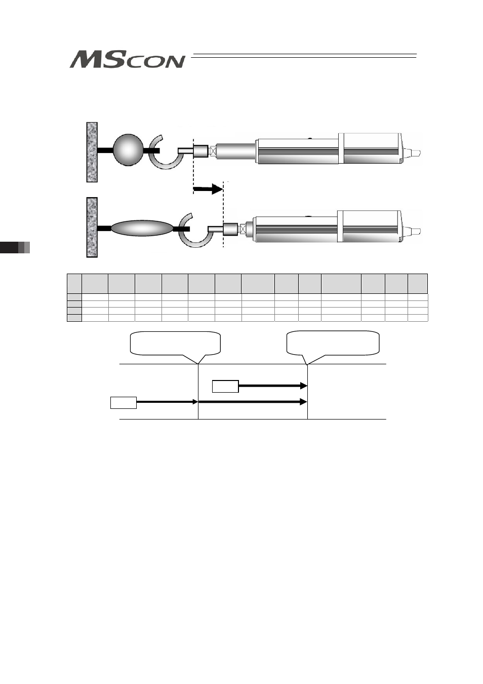
[5] Tension Operation
Image diagram
No.
Position
[mm]
Velocity
[mm/s]
Accele-
ration
[G]
Decele-
ration
[G]
Pressing
[%]
Thresh-
old
[%]
Positioning
width
[mm]
Zone+
[mm]
Zone-
[mm]
Acceleration/
Deceleration
mode
Incre-
mental
Gain
set
Stop
mode
0
1
100.00
250.00
0.20
0.20
0
0
0.10
0.00
0.00
0
0
0
0
2
80.00
250.00
0.20
0.20
50
0
–50.00
0.00
0.00
0
0
0
0
3
Control method
The method of controlling the tension operation is the same as that described in [4] Pressing
operation. The control method is explained below by using the sample position table shown
above.
1) Position No.2 indicates the settings of tension operation. The settings of “Position” and
“Positioning width” show the tension start position and the tension quantity, respectively.
Attach – (minus sign) to the tension quantity. Specify the upper limit of the torque required for
tension in percent (limited current value) in “Pressing”. The speed, acceleration, and
deceleration are the conditions of positioning to the coordinate value (80mm) set in
“Position”.
2) Position No.1 indicates the tension start preparation position. Specify a value larger than the
coordinate value at which the tension provided by position No.2 ends (80 – 50 = 30mm) in
“Position”.
3) First define the positioning in position No.1. Next, the operation in position No.2 moves the
actuator to the position of 80mm at the setting speed and rating torque and change to the
tension operation. The actuator moves by 50mm in the negative direction in the tension
operation. The upper limit of the tensile force is the torque set in percent.
4) In the similar way as pressing, the positioning complete signal is output when the shaft is
stopped by tension (pressing complete). If the actuator cannot be stopped during movement
within the setting positioning width (miss-pressing), it moves by the setting distance to stop
but PEND is not turned ON.
CSTR
Tension Operation
CSTR
Approach operation
Tension Operation
CSTR: Start position
Tension start position
80mm
Tension end position
80 – 50 = 30mm
Position No.1
Position No.2