Chapter 8 troubleshooting, 1 action to be taken upon occurrence of problem – IAI America MSCON User Manual
Page 291
Chapter 8
Troubleshooting
283
Chapter 8 Troubleshooting
8.1 Action to Be Taken upon Occurrence of Problem
Upon occurrence of a problem, take an appropriate action according to the procedure below in
order to ensure quick recovery and prevent recurrence of the problem.
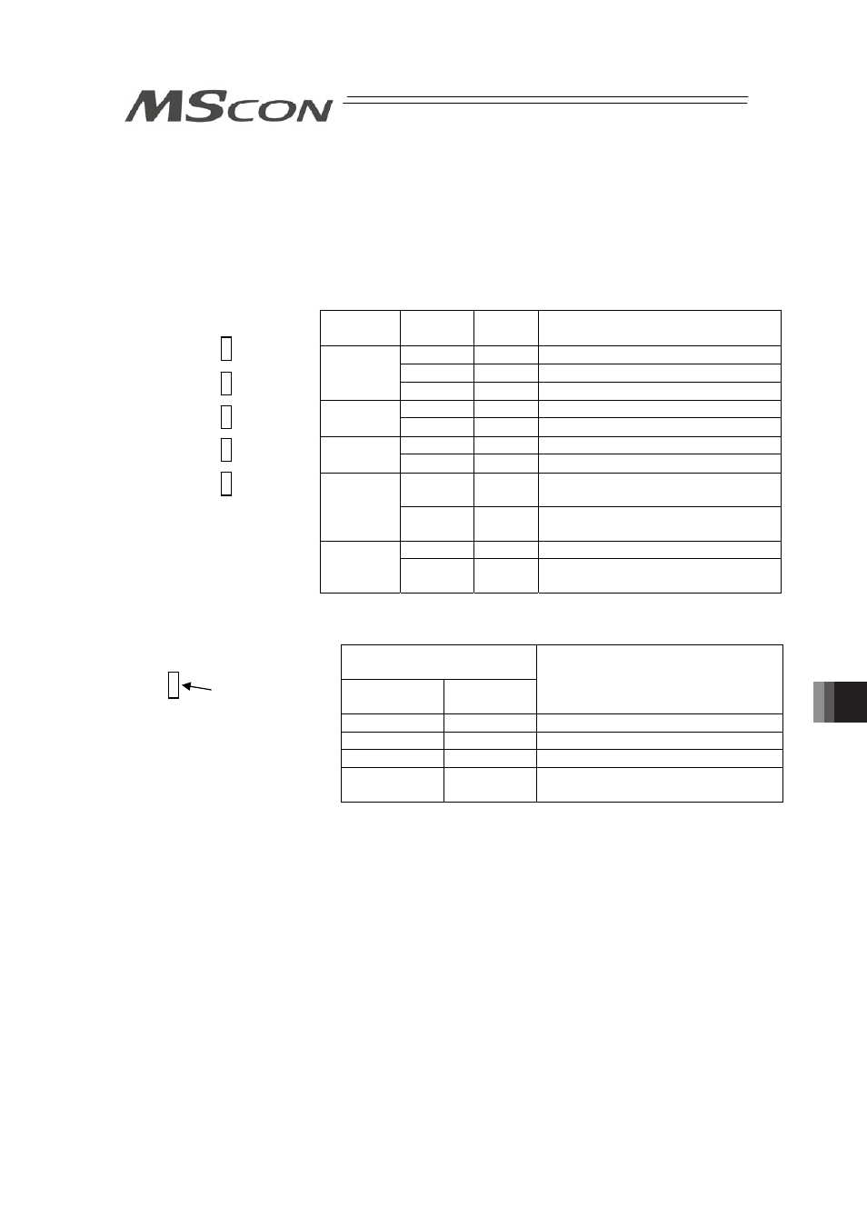
(1) Checking Status (Condition) Display LEDs on Gateway
ALM
RDY
MODE
EMG
T.ERR
C.ERR
(2) Checking Driver Status (Condition) Display LEDs on Each Axis
{
: Illuminating, u: OFF, ڏ: Flashing
LED (SV*/ALM*)
* : Asix No. = 0 to 5
Lamp
condition
Color
Driver status
{
Green
Servo ON
Green
Automatic servo is OFF
u
-
Servo OFF
{
Red
Alarm generated, Emergency-stop
input, Motor driving power OFF
(3) If there is/isn’t an alarm generated in host controller (such as PLC)
(4) Check the voltage of control power supply (24V DC) and drive (motor) power supply
(5) Check the voltage of fieldbus power supply
(6) Check the voltage (24V DC) of the power supply for brake (For the actuator with the
brake).
(7) Alarm Check
(Note1)
Check the alarm code on the teaching tool such as PC software.
(8) Check the connectors for disconnection or connection error.
(9) Check the cables for connection error, disconnection or pinching.
Before performing a continuity check, turn off the power (to prevent electric shocks) and
disconnect the cables of measuring instruments (to prevent accidental power connection
due to sneak current path).
(10) Check the I/O signals.
Using the host controller (PLC, etc.) or a teaching tool such as PC software, check the
presence of inconsistency in I/O signal conditions.
(11) Check the noise elimination measures (grounding, installation of surge killer, etc.).
(12) Check the events leading to the occurrence of problem
(Note 1)
, as well as the operating
condition at the time of occurrence.
(13) Analyze the cause.
Top (for Axis No.
0, 2 and 4)
Bottom (for Axis
No. 1, 3 and 5)
{
: Illuminating, u : OFF
Name
Lamp
condition
Color
Description
{
Green
Normal
{
Orange Alarm issued
ALM/RDY
u
-
Control Power OFF
{
Green
AUTO Mode being selected
MODE
u
-
MANU Mode being selected
{
Red
Emergency-stop input
EMG
u
-
Not an emergency stop
{
Orange Communication error between
Gateway Ù driver board
T.ERR
u
-
Not a communication error
between Gateway Ù driver board
{
Orange Field network communication error
C.ERR
u
-
Not a field network communication
error