IAI America MSCON User Manual
Page 221
3.8 C
ontrol and functions of Input and output signals of Remote I/O Mode
213
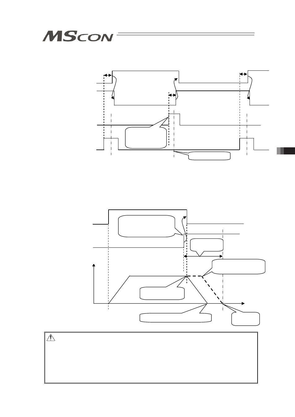
(Example) Repetition of ST1 o ST2 o ST1 o
Insert timer 't if necessary.
[Example of stop position when the ST* signal is turned OFF by the LS* signal]
If the positioning width is set at a position before the original deceleration start position, the
actuator cannot reach the target position.
Caution: (1) If the ST* signal for the position is turned ON after the completion of
positioning, the LS* signal remains ON.
(2) Both the LS* and PEND signals are set to ON in the positioning width zone.
Accordingly, they may be turned ON under operation of the actuator if a large
positioning width is set.
(3) Interlock should be taken so that two or more ST* signals are set to ON
simultaneously. If two or more ST* signals are input simultaneously, they will
be executed according to the following priorities: ST0oST1oST2
Start signal
ST1
(PLCoMSCON)
Turned ON after
entering into
positioning width
zone
Target Position
Position sensing output
LS1
(MSCONoPLC)
Start signal
ST2
(PLCoMSCON)
Position sensing output
LS2
(MSCONoPLC)
Ǎ
t
Ǎ
t
Ǎ
t
Ǎ
t : Time required to certainly reach the target position after the position sensing output LS1 or 2 is turned ON.
Start signal
ST1
(PLCoMSCON)
Turned ON after
entering into
positioning width zone
Target
Position
Position sensing output
LS1
(MSCONoPLC)
Operation of actuator
Stop before target position
Orignal deceleration
start position
Positioning
width
Deceleration
start
Velocity
Move
distance