IAI America MSCON User Manual
Page 59
Chapter 2 Wiring
51
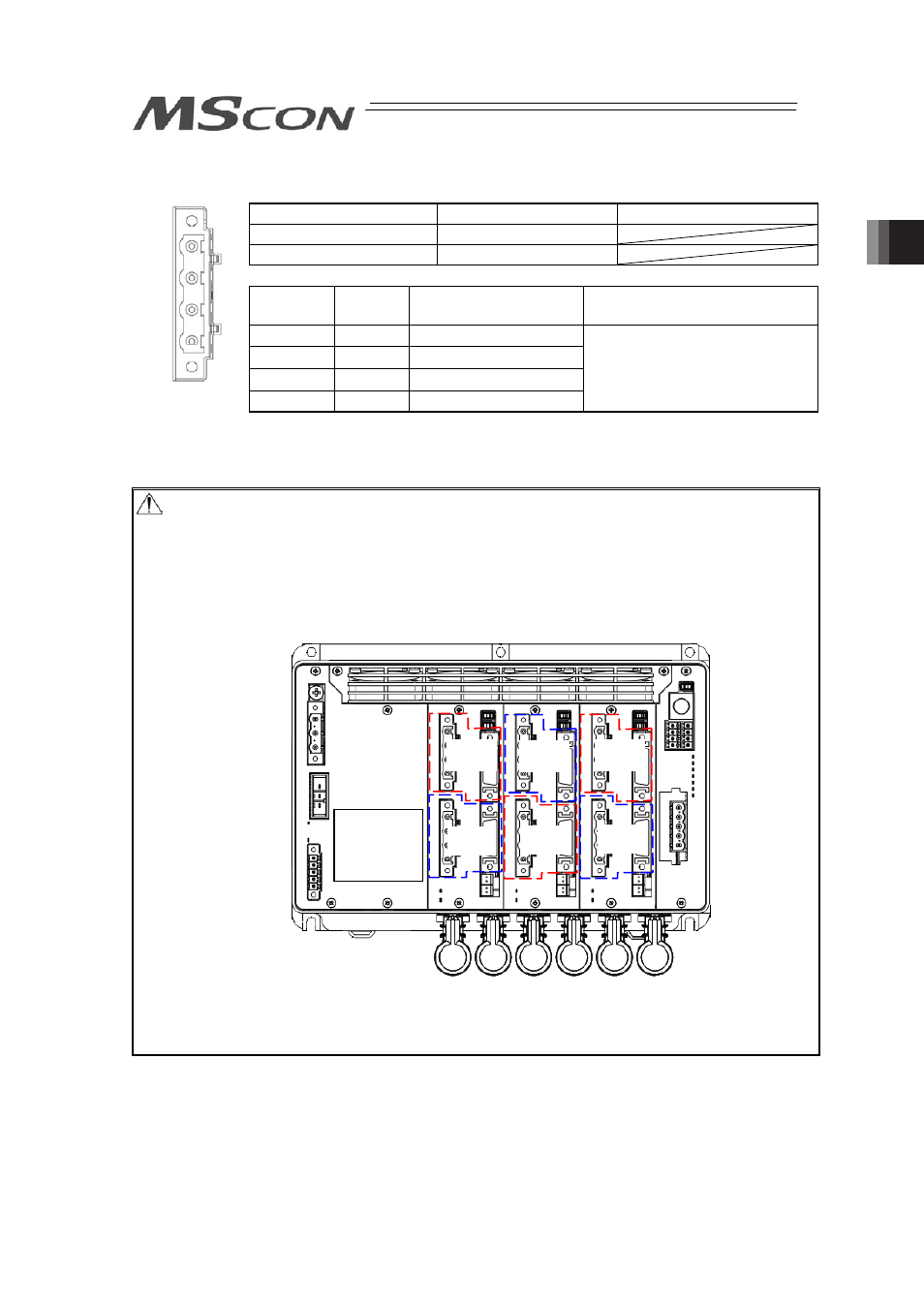
(2) Motor Connector
㩷
㩷
㩷
Motor Connector
Model
Remarks
Cable Side
GIC2.5/4-STF-7.62
Controller Side
GIC2.5/4-GF-7.62
Pin No.
Signal
Name
Contents
Applicable Cable
1
PE
Protective ground terminal
2
U
Motor cable U-phase
3
V
Motor cable V-phase
4
W
Motor cable W-phase
Cable dedicated for IAI products
Caution: There is an axis number shown on the actuator cables (Encoder Cable: PG0 to 5,
Motor Cable: M0 to 5). Refer to the figure below to plug the actuators correctly. Also,
there are the model code and manufacturing number of the connected actuator
printed on the front panel that you can refer to.
There is a risk of wrong operation or operation out of control of actuators if the
connectors are plugged in to the wrong positions.
Check in the instruction manual of each actuator for the details (connection layout
diagram) of each cable.
If an actuator is purchased individually, there is no axis number written on the
connection cable. Check the actuator model code on the front panel and plug in the
connector.
1st Axis
M0 PG0
2nd Axis
M1 PG1
3rd Axis
M2 PG2
4th Axis
M3 PG3
5th Axis
M4 PG4
6th Axis
M5 PG5
Front view of
connector on
controller side
Axis number,
actuator model
code and
manufacturing
number
PE
U
V
W
M