Separate partitions for stereo and mono, Option 2: mono only mode, Managing partitions and signal types – Grass Valley UniConfi NVISION Series v.1.3 User Manual
Page 79
UniConfig Configuration Application • User’s Guide
67
8. Managing Partitions and Signal Types
Setting Up Mono Signal Switching
When entering settings for mixed stereo and mono mode, remember the following:
• Mono operation is only supported with AES3 synchronous hardware or analog audio cards.
• On mono partition 2, the controller input and output end values (the “grayed out” fields) are
double the corresponding stereo values.
• Stereo partition uses physical partition 1, depending on the router control system protocol. (For
more information, see the UniConfig User’s Guide.)
• Mono partitions (left and right) both use physical partition 2, depending on the router control
system protocol. (For more information, see the UniConfig User’s Guide.)
Separate Partitions for Stereo and Mono
Separate level sets can be built for stereo and mono, or stereo and mono can be grouped together in
a single partition set. The advantage to separate sets is less confusion on the router control system
interface
—
only partitions pertinent to a particular destination display. The disadvantage is that tie
lines are needed if stereo devices must be routed to a mono destination.
A single partition set approach places all partitions on display all of the time, possibly creating
some confusion with status or device selection. However, a single partition set is much easier to
manage.
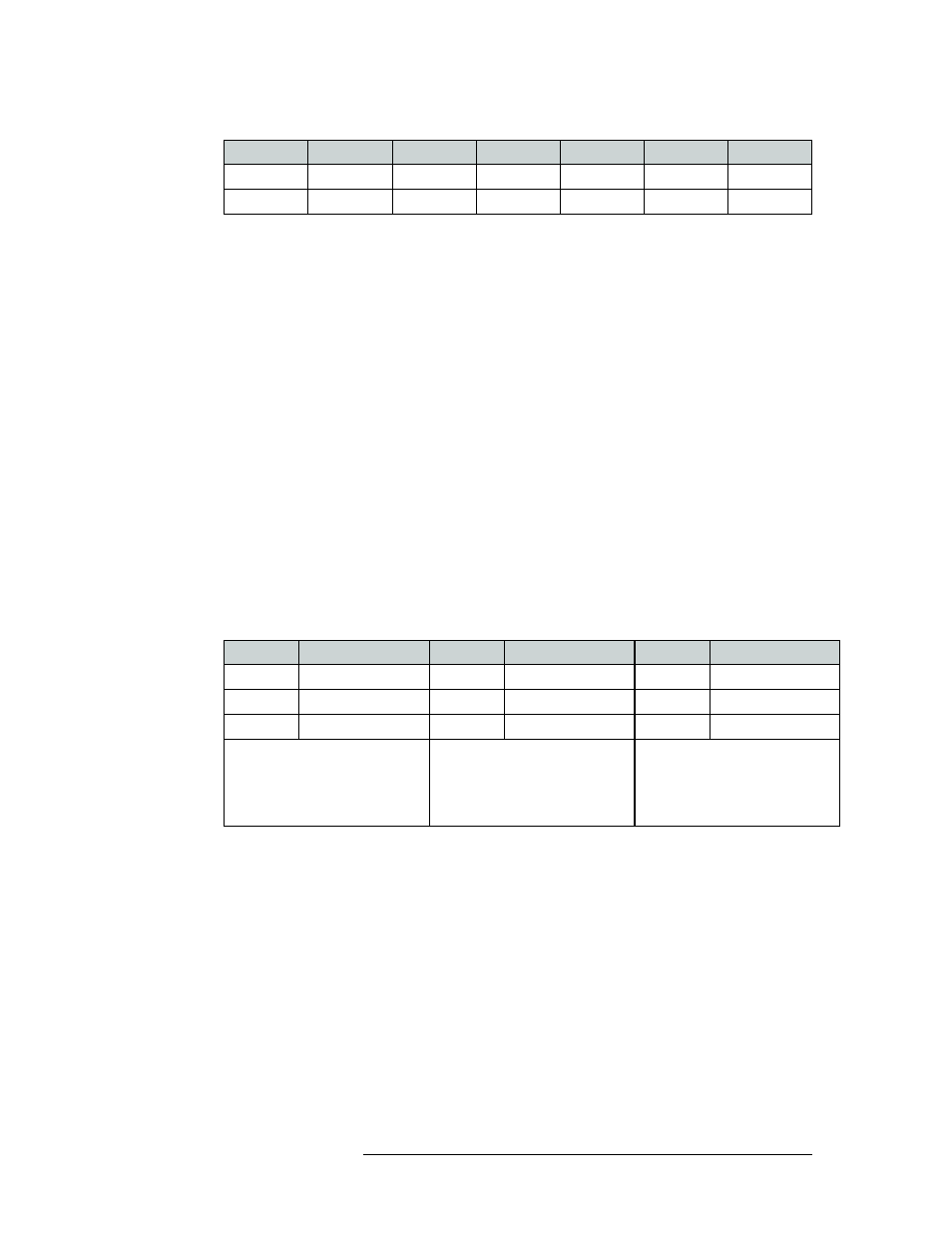
The following illustrates both approaches:
Option 2: Mono Only Mode
Mono-only mode is easy to implement because only a single set of configuration rules are used. In
mono-only mode, devices are represented as two separate partitions on router control system inter-
faces. Mono switching is natively supported. Stereo switches, where left and right channels switch
together, may be ‘simulated’ by populating both partitions of the physical connections table in the
router control system interface with connection information. The left and right levels should be
built as virtual levels using the router control system.
5L
5
5
5
5
5R
6
6
6
6
Status
Partition/Destination
Status
Partition/Destination
Status
Partition/Destination
Device 1
Stereo
Device 1
Stereo
Device 1L
Left
Device 1L
Left
Device 1
Left
Device 1R Right
Device 1R Right
Device 1
Right
Standard Stereo or mono route,
single partition set
Standard Stereo or mono route,
single partition set
(Note status on stereo partition is
determined by the source routed to
the left partition.)
Two partition sets, mono
destination selected, breakaway
established
Device Name Stereo IN
Left Input
Right Input
Stereo OUT
Left Output
Right Output