Setting up communication – Grass Valley UniConfi NVISION Series v.1.3 User Manual
Page 39
UniConfig Configuration Application • User’s Guide
27
6. Setting Up Communication
Entering Initial Serial and Ethernet Settings
5 From the ‘Comm port’ drop-down list, select the communication port number that matches the
port number on the PC running UniConfig and click
OK
.
Or
Click
Cancel
to close the dialog box without saving changes.
6 Again from the menu bar, select ‘Windows > Router Serial Configuration’. The ‘Router Serial
Configuration’ window appears: .
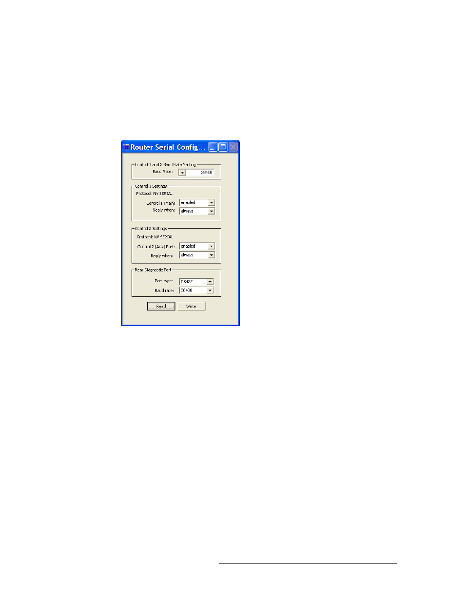
Figure 6-3. Router Serial Configuration Window
The ‘Router Serial Configuration’ window sets serial communication parameters for the router
control system (‘Control Settings’ sections) and for the permanent serial connection labeled
‘DIAG’ located on the rear of the router (‘Rear Diagnostic Port’).
7 On the ‘Router Serial Configuration’ window, select settings as follows. If a serial connection is
not being used for the router control system, skip steps a, b, and c and go directly to step d:
a From the ‘Baud Rate’ drop down list, select a baud rate. By default the baud rate is set to
38400.
b In both the ‘Control 1 Settings’ section and the ‘Control 2 Settings’ section, from the drop-
down list select ‘enabled’ for ‘Control 1 (Main)’ and select ‘enabled’ ‘Control 2 (Aux)
Port’. By default, the ports are set to ‘enabled’.
‘Control 1’ corresponds to the ‘PRIMARY CONTROL’ ‘CTRL 1’ serial connection and
‘Control 2’ corresponds to the ‘PRIMARY CONTROL’ ‘CTRL 2’ serial connection. For
more information, see your router User’s Guide.
c In both the ‘Control 1 Settings’ section and the ‘Control 2 Settings’ section, select a ‘Reply
when’ option from the drop-down lists provided. By default, ‘enabled’ and ‘always’ are
selected.
‘Reply when’ determines how the control card responds to queries and commands sent
through the ‘CTRL’ ports: