How to make a permanent diagnostic connection, Setting up communication – Grass Valley UniConfi NVISION Series v.1.3 User Manual
Page 37
UniConfig Configuration Application • User’s Guide
25
6. Setting Up Communication
Communicating with the Router Through Serial Ports
How to Make a Permanent Diagnostic Connection
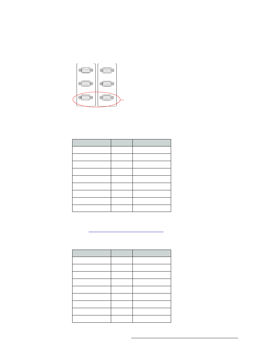
1 Locate the permanent serial ports on the rear of the router, as shown in Figure 6-1. The ports are
labeled ‘DIAG’:
Figure 6-1. Diagnostic Connections (Rear View)
2 Connect to the ‘DIAG’ connection in the ‘PRI CTRL’ section using a DE9 connector and a
serial cable. By default, the ports are typically set for RS-232:
The following lists the wiring for the DE9 pin connectors for RS-232:
For all routers except the NV8288, NV8288-Plus and NV8500 Family, the DE9 connector can
be set for RS-422, but settings changes will need to be made in UniConfig. For more informa-
tion, see
Updating Serial Communication Settings
on page 30. The NV8288, NV8288-Plus and
NV8500 Family routers are always set to RS-232 8, N, 1.
The following lists the wiring for the DE9 pin connectors for RS-422:
CTRL 1
CTRL 2
PRI CTRL
DIAG
Diagnostic
Connections
CTRL 1
CTRL 2
SEC CTRL
DIAG
Hardware End
Pin
Router End
DCD
1
Ground
RXD
2
TXD
TXD
3
RXD
DTR
4
DSR
Signal Ground
5
Signal Ground
DSR
6
DTR
RTS
7
CTS
CTS
8
RTS
Ground
9
Ground
Hardware End
Pin
Router End
Ground
1
Ground
Receive –
2
Transmit –
Transmit +
3
Receive +
Transmit Common
4
Receive Common
N/C
5
N/C
Receive Common
6
Transmit Common
Receive +
7
Transmit +
Transmit –
8
Receive –
Ground
9
Ground