Ec9535 and router baud rates must match, Ec9535 control card diagnostic connections, How to make control card diagnostic connections – Grass Valley UniConfi NVISION Series v.1.3 User Manual
Page 128: Configuring ec9535
116
Rev 1.3 • 14 Dec 09
12. Configuring EC9535
Setting Up EC9535 Communication
In order for the control card and UniConfig to communicate through an Ethernet or serial port
located on the router, the ports need to be initialized. Initialization is performed by setting the nec-
essary information on the control card using UniConfig.
For more information on initial communication, see
Communicating with the Router for the First
EC9535 and Router Baud Rates Must Match
When configuring the EC9535, the EC9535’s ‘CTRL 1’ serial port must be set to the same baud
rate as the controlled router’s ‘CTRL 1’ serial port rate. By default, the NV8288, NV8288-Plus and
NV8500 Family routers have the ‘CTRL 1’ ports set to 38,400 baud. However, the number of des-
tinations that can be switched per frame in a system using a SMS7000 system controller, an
EC9535, and a NV8288, NV8288-Plus or NV8500 Family router is determined by the EC9535 and
the router serial port baud rates. Because higher rates may be used, you may want to set the serial
ports at the highest available rate (115,200 baud) unless doing so results in communication errors.
For information on setting the serial port baud rates for routers, see
EC9535 Control Card Diagnostic Connections
A temporary diagnostic connection can be created using the DE9 port located on the front of the
primary control card. The baud rate for this port is locked to 9600.
How to Make Control Card Diagnostic Connections
1 Facing the front of the EC9535, open the door and locate the primary control card slot. The pri-
mary control card is located on top (above) and the secondary control card is located below.
2 On the front of the control card is a single serial port. Connect to the serial port using a DE9
connector and a serial cable.
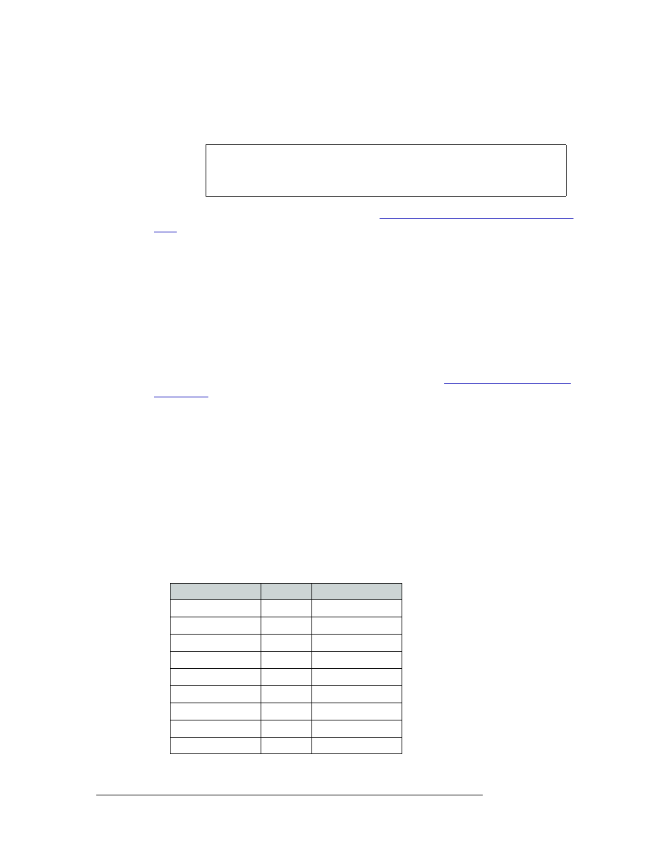
The following lists the DE9 pin connectors for RS-232:
Note
Each control card utilizes its own independent set of EE memory on the mother-
board in the router frame. UniConfig must be used to configure each control card
in the system separately even if the control card is part of a redundant pair.
PC End (DCE)
Pins
Router End (DTE)
DCD
1
Ground
RXD
2
TXD
TXD
3
RXD
DTR
4
DSR
Signal Ground
5
Signal Ground
DSR
6
DTR
RTS
7
CTS
CTS
8
RTS
Ground
9
Ground