Using partitioning addressing, Nv8500 monitor configuration and operation – Grass Valley UniConfi NVISION Series v.1.3 User Manual
Page 145
UniConfig Configuration Application • User’s Guide
133
13. NV8500 Monitor Configuration and Operation
Using Partitioning Addressing
7 From the ‘Signal Type’ drop-down list, select the signal type ‘Monitor’.
8 Click
Write All
to writes changes to the control card.
9 Repeat steps 2 through 8 for each control card being updated.
Using Partitioning Addressing
Third-party control systems or software drivers may be used to control the monitoring of router
inputs and outputs. This section assumes that the control card in the router is running application
version 14.0.0.xx and newer (matching FPGA versions: CPLD, SV0900-07, SV0901-06 and
newer), which supports the monitoring of both input and output signals.
Controlling which inputs and outputs are switched to the different monitor outputs is accomplished
using the same switching methods for controlling crosspoints. To do this, the following steps must
occur:
1 The router’s inputs and outputs are partitioned and assigned a unique level. A level is simply a
way of defining an organizational partition within a router.
2 The level is assigned the unique signal type value “Monitor.”
3 Save the new partition configuration to the router.
4 Issue a standard ‘take’ command from the control system to the router’s Monitor partition, as
defined in the protocol being used. In most cases this will be the NVISON Ethernet or Serial
protocol. (See the UniConfig User’s Guide for more information on partitioning and signal
types.)
Each router in the NV8500 Family—NV8144, NV8280/NV8280-Plus and NV8576/NV8576-
Plus—has subtle differences when setting up and controlling monitors. Developers writing control
software, or system engineers using one of the router’s supported third-party protocols, must be
aware of the differences when performing Monitor ‘takes’. In addition, to maximize efficiency,
only one signal is sent from each input or output card to the monitor card for forwarding to moni-
toring equipment. This means that only one signal from each input card or output card is monitored
at any given time. Programmers should be aware of these limitations when writing control soft-
ware. For more information, see
The format of a ‘take’ command may vary depending on the protocol used, but the command
always sends the router the level value of the partition, the Output value, and the Input value. The
‘take’ commands causes the Input value to be switched to the Output value, and because it is in the
Monitor partition (i.e., the level with the signal type ‘Monitor” assigned), the router knows to send
the input or output to the monitor card in the router.
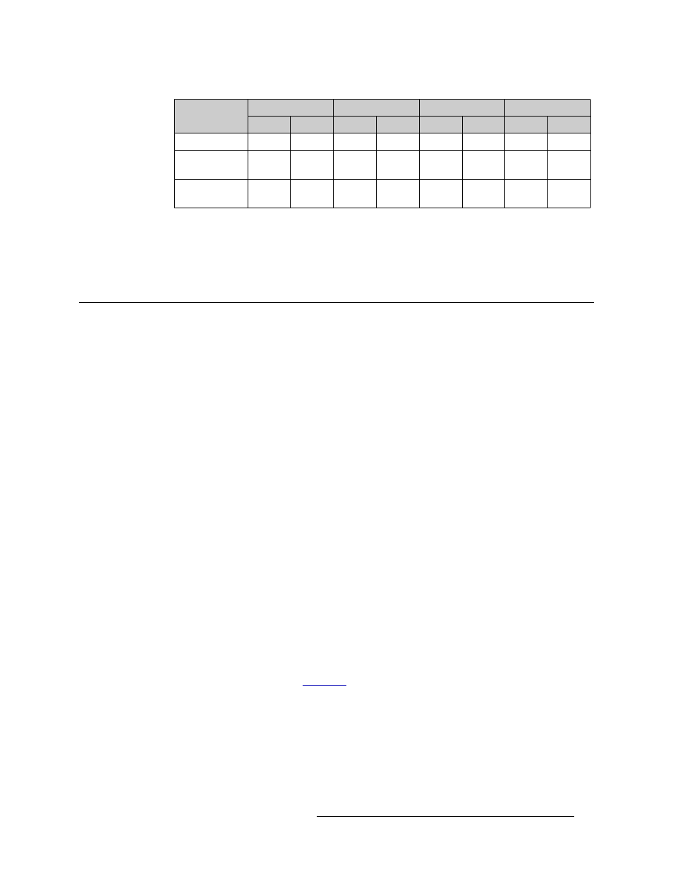
Router
Physical Inputs
Controller Inputs
Physical Outputs
Controller Outputs
Start
End
Start
End
Start
End
Start
End
NV8144
1
144
1
144
1
4
1
4
NV8280/
NV8280-Plus
1
576
1
576
1
4
1
4
NV8576/
NV8576-Plus
1
1152
1
1152
1
4
1
4