Grass Valley UniConfi NVISION Series v.1.3 User Manual
Uniconfig configuration application, User’s guide
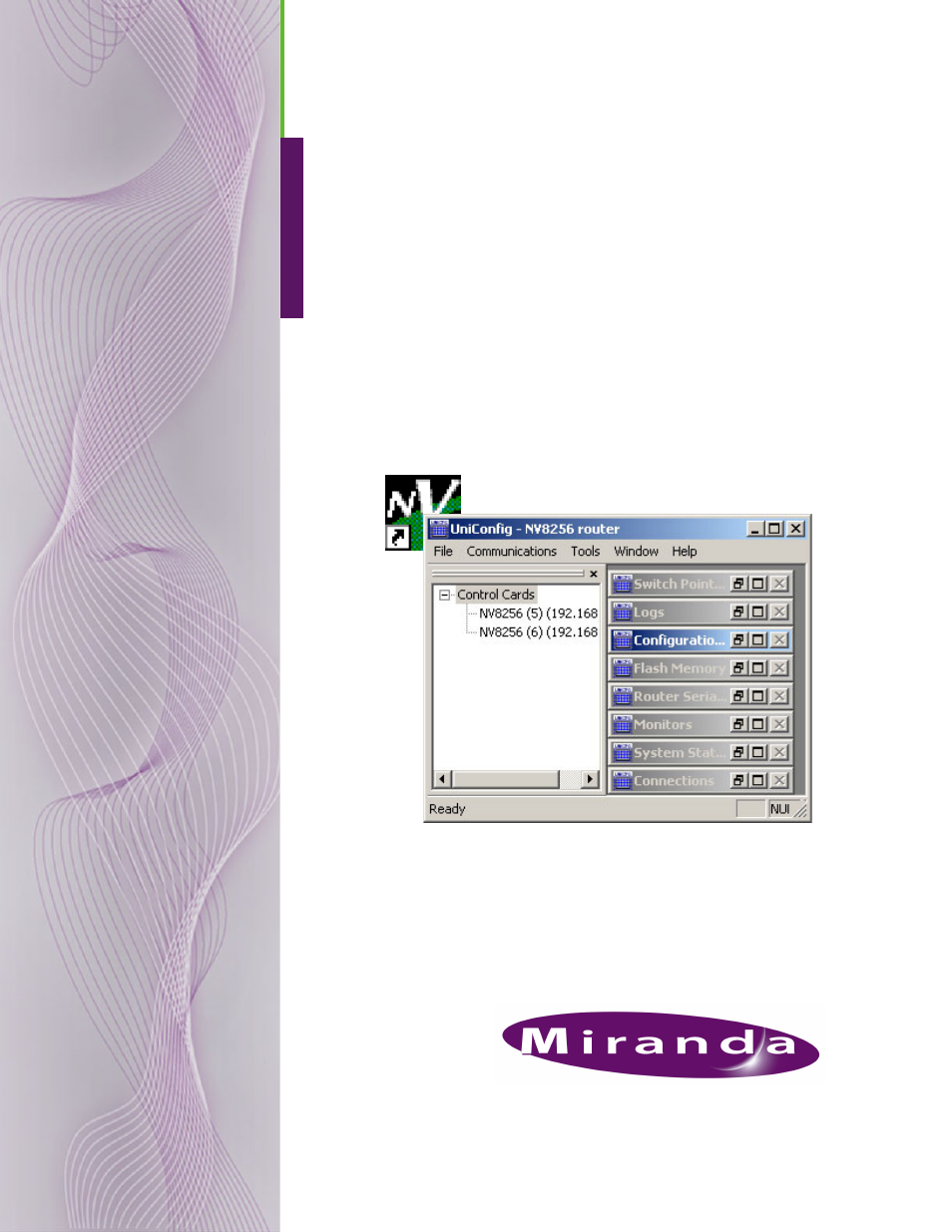
Table of contents
Document Outline
- Table of Contents
- 1. Preface
- 2. Introduction
- 3. UniConfig Basics
- 4. Configuration Basics
- Before Starting Configuration
- Launching UniConfig
- Selecting a Control Card
- Viewing Configurations
- Writing Changes to the Control Card
- Applying Configurations to Another Control Card (Save As)
- How to Apply a Configuration to Another Control Card
- 2 Select a control card. (See Selecting a Control Card on page 10.)
- 3 From the menu bar, select ‘Windows > Configuration’. The ‘Configuration’ window appears, as shown in Figure 4-1 on page 11.
- 4 Click Read All. Current configuration settings for the selected control card populate the ‘Configuration’ window fields.
- 5 From the menu bar, select ‘Tools > Options’. The ‘Configuration Options’ dialog box appears:
- 6 Uncheck the ‘Auto refresh when selecting different node’ check box. By default this box is checked. When checked, whenever a c...
- 7 Click OK to save changes and close the dialog box.
- 8 Select the control card to which you want the current configuration settings applied. (See Selecting a Control Card on page 10.)
- 9 Important: If you are using an Ethernet connection, be sure to up the IP address in the ‘IP Address’ field on the ‘Configurati...
- 10 On the ‘Configuration’ window, click Write All. The current configuration settings are sent to the currently selected control card.
- How to Apply a Configuration to Another Control Card
- Viewing ‘Write All’ Sequence
- How to View Write Sequence Progress
- 2 Select a control card. (See Selecting a Control Card on page 10.)
- 3 From the menu bar, select ‘Windows > Configuration’. The ‘Configuration’ window appears, as shown in Figure 4-1 on page 11.
- 4 Click Read All. Current configuration settings for the selected control card populate the ‘Configuration’ window fields.
- 5 From the menu bar, select ‘Tools > Options’. The ‘Configuration Options’ dialog box appears:
- 6 Check the ‘Show advanced Serial EE settings’ check box. By default this box is not checked. When checked, more options appear: .
- 7 Check the ‘Display diagnostic screen during updates’ check box. The next time Write All is clicked, the ‘Serial EE Write Status’ dialog box displays the status of data being written to the control card.
- 8 Click OK to save changes and close the dialog box.
- How to View Write Sequence Progress
- Applying Only Current Changes or All Settings
- How to Write Current or All Settings to the Control Card
- 2 Select a control card. (See Selecting a Control Card on page 10.)
- 3 From the menu bar, select ‘Windows > Configuration’. The ‘Configuration’ window appears, as shown in Figure 4-1 on page 11.
- 4 Click Read All. Current configuration settings for the selected control card populate the ‘Configuration’ window fields.
- 5 From the menu bar, select ‘Tools > Options’. The ‘Configuration Options’ dialog box appears:
- 6 Check the ‘Show advanced Serial EE settings’ check box. By default this box is not checked. When checked, more options appear: .
- 7 In the ‘Serial EE data updates’ section, select what data is sent to the control card when Write All on the ‘Configuration’ window is clicked:
- 8 Click OK to save changes and close the dialog box.
- How to Write Current or All Settings to the Control Card
- 5. Installation
- Preparing for Installation
- Installing UniConfig
- How to Install UniConfig
- 2 Open the CD’s top-level directory. Then open the ‘Software’ sub-folder. Find UniConfig_Install.exe. That is the installer. (You may copy the file to your hard drive if you want.) Double-click the installer, either on the CD or on your hard drive.
- 3 The UniConfig installer will launch:
- 4 Follow the instructions, clicking ‘Next’ to proceed from step to step. The actual installation takes about 30 seconds. By default, the installer creates an entry in the Windows ‘Start’ menu and also creates a shortcut on your desktop:
- How to Install UniConfig
- 6. Setting Up Communication
- Communicating with the Router for the First Time
- Communicating with a Router Control System
- Communicating with the Router Through Serial Ports
- EC9535 Note
- Control Card Serial Port (Temporary Connection)
- How to Make a Temporary Serial Connection
- 2 On the front of the control card, connect to the DE9 connection using a DE9 connector and a serial cable set for EIA-232.
- 3 Connect the other end of the cable to the hardware running the UniConfig application using a DE9 connector. (See Installing UniConfig on page 19.)
- Router Serial ‘DIAG’ Port (Permanent Connection)
- Entering Initial Serial and Ethernet Settings
- 2 Serial connection settings are entered for UniConfig.
- 3 Ethernet connection settings are entered for the router so that the router can communicate over a network. These settings are used by the router control system if the router control system uses an Ethernet connection.
- 4 Ethernet connection settings are entered for UniConfig so that UniConfig can communicate with the router control cards through a network. Routers are added to a network through a separate procedure. (See Adding a Control Card to a Network on page 41.)
- How to Enter Communication Parameters
- 2 Launch UniConfig. (See Launching UniConfig on page 9.)
- 3 From the menu bar, select ‘Communications > Serial’. This informs UniConfig that communication with the router is through a serial port.
- 4 Again from the menu bar, select ‘Communication > Setup’. The ‘Serial Communications’ dialog box appears:
- 5 From the ‘Comm port’ drop-down list, select the communication port number that matches the port number on the PC running UniConfig and click OK.
- 6 Again from the menu bar, select ‘Windows > Router Serial Configuration’. The ‘Router Serial Configuration’ window appears: .
- 7 On the ‘Router Serial Configuration’ window, select settings as follows. If a serial connection is not being used for the router control system, skip steps a, b, and c and go directly to step d:
- 8 Again from the menu bar, select ‘Window > Configuration’. The ‘Configuration’ window appears, as shown in Figure 6-4. Using th...
- 9 On the ‘Configuration’ window, select settings as follows:
- 10 Again from the menu bar, select ‘Communication > Ethernet’. This informs UniConfig that communication with the router is thro...
- 11 Again from the menu bar, select ‘Communication > Setup’. The ‘Ethernet Communication’ dialog box appears:
- 12 On the ‘Ethernet Communication’ dialog box, select settings as follows:
- 13 If a secondary (optional for redundancy) control card is installed, make a temporary connection to the secondary control card and repeat steps 2 though 12.
- Updating Ethernet Communication Settings
- How to Update Ethernet Communication Settings
- 2 Select a control card. (See Selecting a Control Card on page 10.)
- 3 Update Ethernet settings as described in steps 8-10, under Entering Initial Serial and Ethernet Settings on page 26.
- 4 A dialog box appears asking if you want to reboot. Reboot at this time.
- 5 Repeat steps 2-4 for each control card being updated.
- How to Update Ethernet Communication Settings
- Updating Serial Communication Settings
- How to Update Serial Communication Settings
- 2 Select a control card. (See Selecting a Control Card on page 10.)
- 3 Update serial settings as described in steps 3-7, under Entering Initial Serial and Ethernet Settings on page 26.
- 4 A dialog box appears asking if you want to reboot. Reboot at this time.
- 5 Repeat steps 2-4 for each control card being updated.
- How to Update Serial Communication Settings
- Retaining Serial Port Settings
- How to Retain the Most Current Serial Communication Settings
- 2 Select a control card. (See Selecting a Control Card on page 10.)
- 3 From the menu bar, select ‘Tools > Options’. The ‘Configuration Options’ dialog box appears:
- 4 Check the ‘Retain serial port settings’ check box. By default this box is checked.
- 5 Click OK to save changes and close the dialog box.
- 6 Repeat steps 2 through 5 for each control card being updated.
- How to Retain the Most Current Serial Communication Settings
- Viewing Current Communication Settings
- Viewing Serial Settings for UniConfig
- How to View Current UniConfig Serial Communication Settings
- 2 Select a control card. (See Selecting a Control Card on page 10.)
- 3 Again from the menu bar, select ‘Communication > Setup’. The ‘Serial Communications’ dialog box appears displaying current ‘Comm port’ and ‘Baud rate’ settings:
- 4 Click Cancel to close the dialog box.
- Viewing Serial Settings for the Router
- How to view current router serial communication settings
- 2 Select a control card. (See Selecting a Control Card on page 10.)
- 3 Again from the menu bar, select ‘Windows > Router Serial Configuration’. The ‘Router Serial Configuration’ window appears: .
- 4 Click Read. The current serial connection settings display in the fields provided.
- Viewing Ethernet Settings for UniConfig
- How to View Current UniConfig Ethernet Communication Settings
- 2 Select a control card. (See Selecting a Control Card on page 10.)
- 3 From the menu bar, select ‘Communication > Ethernet’. This informs UniConfig that communication with the router is through an Ethernet port. The ‘Control Card’ pane appears on the left-hand side of the UniConfig screen.
- 4 Again from the menu bar, select ‘Communication > Setup’. The ‘Ethernet Communication’ dialog box appears:
- 5 Click Cancel to close the dialog box.
- Viewing Ethernet Settings for the Router
- How to View Basic Ethernet Communication Settings
- 2 Select a control card. (See Selecting a Control Card on page 10.)
- 3 Again from the menu bar, select ‘Communications > Setup’. The ‘Configuration’ window appears:
- 4 Click Read All. The ‘Configuration’ window populates with the current router configuration and Ethernet settings.
- How to View Expanded Ethernet Communication Settings
- 2 Select a control card. (See Selecting a Control Card on page 10.)
- 3 From the menu bar, select ‘Windows > Configuration’. The ‘Configuration’ window appears, as shown in Figure 6-4.
- 4 Click Read All. Current configuration settings for the selected control card populate the ‘Configuration’ window fields.
- 5 From the menu bar, select ‘Tools > Options’. The ‘Configuration Options’ dialog box appears:
- 6 Check the ‘Show advanced Ethernet settings’ check box. By default this box is not checked.
- 7 Click OK to save changes and close the dialog box.
- 8 The ‘Configuration’ window displays advanced settings in the ‘Router Ethernet Settings’ section:
- 9 (Optional) Enable a gateway. See Setting Up a Gateway on page 45.
- Viewing Serial Settings for UniConfig
- Removing Communication Parameters
- How to Remove a Control Card from the Network
- 2 Select a control card. (See Selecting a Control Card on page 10.)
- 3 From the menu bar, select ‘Windows > Configuration’. The ‘Configuration’ window appears, as shown in Figure 6-4.
- 4 (Optional) Click Read All. The ‘Configuration’ window populates with the current router configuration and Ethernet settings.
- 5 In the ‘Router Ethernet Settings’ section, select the ‘Disable’ radio button. This disables the control card from being able to communicate with UniConfig through the Ethernet.
- 6 Repeat steps 2-5 for each control card being removed.
- How to Remove a Control Card from the Network
- Selecting Bus for Serial Router Control System Connection
- How to Select a Bus
- 2 Select a control card. (See Selecting a Control Card on page 10.)
- 3 Again from the menu bar, select ‘Communications > Setup’. The ‘Configuration’ window appears:
- 4 Select the ‘10bse2’ or ‘Internal’ radio button:
- 5 Click Write All to send changes to the control card.
- 6 Repeat steps 2-5 for each control card being updated.
- How to Select a Bus
- 7. Managing Control Cards on a Network
- Using Ethernet or Serial Connection
- Network Basics
- Adding a Control Card to a Network
- How to Add a Control Card to a Network
- 2 Connect the router and the PC to the network. It is recommended that a hub or switch be used.
- 3 Launch and connect to UniConfig using an Ethernet connection. (See Launching UniConfig on page 9.)
- 4 Open the ‘Control Cards’ pane. (See Control Cards Pane on page 7.)
- 5 Using the ‘Control Cards’ pane, add router control cards to the network:
- 6 To close the ‘Control Card Configuration’ dialog box, click X in the upper, right-hand corner.
- How to Add a Control Card to a Network
- Communicating with a Control Card on a Network
- How to Communicate with a Device on the Network
- 2 Open the ‘Control Cards’ pane. (See Control Cards Pane on page 7.) The ‘Control Card’ pane appears, as shown in Figure 7-1.
- 3 Select a control card. (See Selecting a Control Card on page 10.)
- 4 On the ‘Control Cards’ pane, select the control card you want to communicate with.
- 5 Click Read All. The ‘Configuration’ window populates with the current router configuration and serial and Ethernet settings and initiates communication with the selected control card.
- How to Communicate with a Device on the Network
- Viewing Control Cards on a Network
- Moving the ‘Control Cards’ Pane
- Updating Control Cards on a Network
- How to Update Control Card Settings on a Network
- 2 Open the ‘Control Cards’ pane. (See Control Cards Pane on page 7.) The ‘Control Card’ pane appears, as shown in Figure 7-1.
- 3 Select a control card. (See Selecting a Control Card on page 10.)
- 4 On the ‘Control Card’ pane, right-click on the control card you want to update and from the pop-up menu select ‘Edit Name and IP Address’. The ‘Control Card Configuration’ dialog box appears, as shown in Figure 7-2.
- 5 (Optional) On the ‘Configuration’ window, click Read All to view current router configuration and Ethernet settings.
- 6 Update the ‘IP Address’ and ‘Name’ in the fields provided and click OK.
- 7 To close the ‘Control Card Configuration’ dialog box, click X in the upper, right-hand corner.
- 8 Repeat steps 2 through 7 for each control card being updated.
- How to Update Control Card Settings on a Network
- Removing Control Cards from a Network
- How to Remove a Control Card from the Network
- 2 Open the ‘Control Cards’ pane. (See Control Cards Pane on page 7.) The ‘Control Card’ pane appears, as shown in Figure 7-1.
- 3 Select a control card. (See Selecting a Control Card on page 10.)
- 4 On the ‘Control Card’ pane, right-click on the control card you want to delete and from the pop- up menu select ‘Delete.
- 5 Again from the menu bar, select ‘Windows > Configuration’. The ‘Configuration’ window appears, as shown in Figure 7-1.
- 6 (Optional) Click Read All. The ‘Configuration’ window populates with the current router configuration and Ethernet settings.
- 7 In the ‘Router Ethernet Settings’ section, select the ‘Disable’ radio button. This removes the control card from the network.
- 8 Repeat steps 2-7 for each control card being removed.
- How to Remove a Control Card from the Network
- Setting Up a Gateway
- How to Set Up a Gateway
- 2 Select a control card. (See Selecting a Control Card on page 10.)
- 3 From the menu bar, select ‘Windows > Configuration’. The ‘Configuration’ window appears, as shown in Figure 7-1.
- 4 Click Read All. Current configuration settings for the selected control card populate the ‘Configuration’ window fields.
- 5 From the menu bar, select ‘Tools > Options’. The ‘Configuration Options’ dialog box appears:
- 6 Check the ‘Show advanced Ethernet settings’ check box. By default this box is not checked.
- 7 Click OK to save changes and close the dialog box.
- 8 (Optional) Enter a ‘Router Name’ in the field provided. This is used to identify the control card by name instead of IP address.
- 9 Check the ‘Enable Gateway’ check box.
- 10 Enter the IP address for the gateway in the ‘Gateway IP Addr” field.
- 11 Click Write All to write changes to the control card.
- 12 Repeat steps 2-11 for each control card being updated.
- How to Set Up a Gateway
- 8. Managing Partitions and Signal Types
- About Partitions
- Signal Types
- About Output Follow Mode
- About Data X/Y Mode
- About Machine Control Modes
- Setting Up Partitions
- Standalone Routers
- How to Set Up Partitions for a Standalone Router
- 2 Select a control card. (See Selecting a Control Card on page 10.)
- 3 From the menu bar, select ‘Windows > Configuration’. The ‘Configuration’ window appears:
- 4 The NV5256, NV7256-Plus, NV7512, NV8256-Plus, NV8288-Plus and the NV8500 Family (in expanded mode) routers can be connected to...
- 5 Click Read All. The ‘Configuration’ window populates with the current router configuration and Ethernet settings. If no prior configuration is stored, many of the fields are blank.
- 6 To set up a partition, enter ‘Level’, ‘Physical Inputs’, ‘Controller Inputs’, ‘Physical Outputs’ and ‘Controller Output’ infor...
- 7 From the ‘Signal Type’ drop-down list, select a signal type for each partition. Select the signal type on the same row listing the partition information.
- 8 Click Write All to writes changes to the control card.
- 9 Repeat steps 2 through 8 for each control card being updated.
- Multiple Frames
- How to Set Up Partitions for a Master Router
- 2 Select the primary control card on the router acting as the master router. (See Selecting a Control Card on page 10.)
- 3 From the menu bar, select ‘Windows > Configuration’. The ‘Configuration’ window appears displaying an ‘Expansion’ section:
- 4 Click Read All. The ‘Configuration’ window populates with the current router configuration and Ethernet settings.
- 5 Select the ‘Main -Expanded’ radio button in the ‘Expansion’ section. This sets the control card on the router as the master (or main) control card controlling all slave routers and expands the ‘Expansion’ section:
- 6 For ‘Local Inputs’ and ‘Outputs’, enter a ‘Start’ and ‘End’ number in the corresponding fields. The inputs are the total numbe...
- 7 Enter a unique ‘Index’ number in the field provided in the ‘Expansion’ section. This number acts as an identification number in UniConfig. The number must be unique and not assigned to any other router.
- 8 To set up a partition, enter ‘Level’, ‘Physical Inputs’, ‘Controller Inputs’, ‘Physical Outputs’ and ‘Controller Output’ infor...
- 9 From the ‘Signal Type’ drop-down list, select a signal type for each partition, such as ‘Digital Video’. Select the signal type on the same row listing the partition information.
- 10 Click Write All to write changes to the control card.
- 11 Repeat steps 2 through 10 for each control card on the master router.
- How to Set U p Partitions for Slave Routers
- 2 Select a control card on the router acting as the slave router. (See Selecting a Control Card on page 10.)
- 3 From the menu bar, select ‘Windows > Configuration’. The ‘Configuration’ window appears displaying an ‘Expansion’ section:
- 4 Click Read All. The ‘Configuration’ window populates with the current router configuration and Ethernet settings.
- 5 Select the ‘Slave - Expanded’ radio button in the ‘Expansion’ section. This sets the control card on the router as the slave control card controlled by the master (or main) router and expands the ‘Expansion’ section:
- 6 For ‘Local Inputs’ and ‘Outputs’, enter a ‘Start’ and ‘End’ number in the corresponding fields. The inputs are the total numbe...
- 7 Enter a unique ‘Index’ number in the field provided in the ‘Expansion’ section. This number acts as an identification number in UniConfig. The number must be unique and not assigned to any other router.
- 8 Click Write All to send changes to the control card.
- 9 Repeat steps 2 through 8 for each control card on all slave routers.
- Standalone Routers
- Updating Partitions
- How to Update Partitions
- 2 Select a control card. (See Selecting a Control Card on page 10.)
- 3 From the menu bar, select ‘Windows > Configuration’. The ‘Configuration’ window appears, as shown in Figure 8-2 on page 53.
- 4 Click Read All. The ‘Configuration’ window populates with the current router configuration and Ethernet settings.
- 5 In the ‘Level’, ‘Physical Inputs’, ‘Controller Inputs’, ‘Physical Outputs’ and ‘Controller Output’, update information as need...
- 6 From the ‘Signal Type’ drop-down list, update the signal type for each partition as needed as described in step 7 in How to Se...
- 7 Click Write All to send changes to the control card.
- 8 Repeat steps 2 through 7 for each control card being updated.
- How to Update Partitions
- Setting Up Mono Signal Switching
- 9. Managing Switch Point Settings
- About Video Signal Fields and Frames
- About Redundant and Dual Video References
- Setting Up Switch Points
- How to Select Switch Point Settings for the NV5100MC or NV5128 Router
- 2 Select a control card. (See Selecting a Control Card on page 10.)
- 3 From the menu bar, select ‘Window > Switch Point Setup’. The ‘Switch Point Setup’ window appears displaying current output settings for the router being configured:
- 4 In the ‘Output Range’ section, enter a ‘Start’ and ‘End’ output signal number in the fields provided and click Read Outputs. Outputs corresponding to the range entered display in the ‘Select Outputs to edit’ pane with default settings.
- 5 In the ‘Select Outputs to edit’ pane, select the outputs being updated:
- 6 In the ‘Set selection(s) to’ section, check each check box to apply re-clocking and switching on the SD or HD line for the selected outputs.
- 7 In the ‘Dual Video Reference Option’ section, select ‘Redundant’ or ‘Dual’.
- 8 In the ‘NTSC/PAL Reference Options’ section, select the radio button corresponding to the signal type being used as a video re...
- 9 Click Apply Changes to Selected Outputs, or from the menu bar select ‘Edit > Apply Changes’, to apply your changes to the selected outputs. This does not write your changes to the control cards. The changes display in the right-hand field.
- 10 Click Write All, or from the menu bar select ‘Edit > Write Changes’, to send your changes to the control card.
- 11 Repeat steps 2-10 for each control card being updated.
- How to Select Switchpoint Settings for the NV7256 and NV7256-Plus Router
- 2 Select a control card. (See Selecting a Control Card on page 10.)
- 3 From the menu bar, select ‘Window > Switch Point Setup’. The ‘Switch Point Setup’ window appears displaying current output settings for the router being configured:
- 4 In the ‘Output Range’ section, enter a ‘Start’ and ‘End’ output signal number in the fields provided and click Read Outputs. Outputs corresponding to the range entered display in the ‘Select Outputs to edit’ pane with default settings.
- 5 In the ‘Select Outputs to edit’ pane, select the outputs being updated:
- 6 In the ‘Set selection(s) to’ section, check to have video signals ‘Switch on Frame Boundary’ or ‘Switch on Field Boundary’. For more information, see About Video Signal Fields and Frames on page 71.
- 7 In the ‘Dual Video Reference Option’ section, select ‘Redundant’ or ‘Dual’.
- 8 Click Apply Changes to Selected Outputs, or from the menu bar select ‘Edit > Apply Changes’, to apply your changes to the selected outputs. This does not write your changes to the control cards. The changes display in the right-hand field.
- 9 Click Write All, or from the menu bar select ‘Edit > Write Changes’, to send changes to the control card.
- 10 Repeat steps 2-8 for each control card being updated.
- How to Select Switch Point Settings for the NV7512 Router
- 2 Select a control card. (See Selecting a Control Card on page 10.)
- 3 From the menu bar, select ‘Window > Switch Point Setup’. The ‘Switch Point Setup’ window appears displaying current output settings for the router being configured:
- 4 In the ‘Output Range’ section, enter a ‘Start’ and ‘End’ output signal number in the fields provided and click Read Outputs. Outputs corresponding to the range entered display in the ‘Select Outputs to edit’ pane with default settings.
- 5 In the ‘Select Outputs to edit’ pane, select the outputs being updated:
- 6 In the ‘Set selection(s) to’ section, check each check box to apply ‘Enable Crossfade’ or ‘Disable Crossfade’ to the selected outputs. ‘Enable’ or ‘Disable’ displays in the ‘Crossfade’ column.
- 7 In the ‘Dual Video Reference Option’ section, select ‘Redundant’ or ‘Dual’.
- 8 Click Apply Changes to Selected Outputs, or from the menu bar select ‘Edit > Apply Changes’, to apply your changes to the selected outputs. This does not write your changes to the control cards. The changes display in the right-hand field.
- 9 Click Write All, or from the menu bar select ‘Edit > Write Changes’, to send changes to the control card.
- 10 Repeat steps 2-8 for each control card being updated.
- How to Select Switch Point Settings for the NV8256-Plus Router
- 2 Select a control card. (See Selecting a Control Card on page 10.)
- 3 From the menu bar, select ‘Window > Switch Point Setup’. The ‘Switch Point Setup’ window appears displaying current output settings for the router being configured:
- 4 In the ‘Output Range’ section, enter a ‘Start’ and ‘End’ output signal number in the fields provided and click Read Outputs. Outputs corresponding to the range entered display in the ‘Select Outputs to edit’ pane with default settings.
- 5 In the ‘Select Outputs to edit’ pane, select the outputs being updated:
- 6 In the ‘Set selection(s) to’ section, check each check box to apply re-clocking, frame or field boundary, and the SD or HD line switching for the selected outputs.
- 7 In the ‘Dual Video Reference Option’ section, select ‘Redundant’ or ‘Dual’.
- 8 In the ‘NTSC/PAL Reference Options’ section, select the radio button corresponding to the signal type being used as a video reference: ‘1080i’, ‘720p’ or ‘1080p’. This signal will be used as the switching reference.
- 9 Click Apply Changes to Selected Outputs, or from the menu bar select ‘Edit > Apply Changes’, to apply your changes to the selected outputs. This does not write your changes to the control cards. The changes display in the right-hand field.
- 10 Click Write All, or from the menu bar select ‘Edit > Write Changes’, to send changes to the control card.
- 11 Repeat steps 2-9 for each control card being updated.
- How to Select Switch Point Settings for the NV8288 and NV8288-Plus Routers
- 2 Select a control card. (See Selecting a Control Card on page 10.)
- 3 From the menu bar, select ‘Window > Switch Point Setup’. The ‘Switch Point Setup’ window appears displaying current output settings for the router being configured:
- 4 In the ‘Output Range’ section, enter a ‘Start’ and ‘End’ output signal number in the fields provided and click Read Outputs. Outputs corresponding to the range entered display in the ‘Select Outputs to edit’ pane with default settings.
- 5 In the ‘Select Outputs to edit’ pane, select the outputs being updated:
- 6 In the ‘Set selection(s) to’ section, check each check box to apply a video reference, re-clocking and switching on the SD or HD line for the selected outputs.
- 7 In the ‘Dual Video Reference Option’ section, select ‘Redundant’ or ‘Dual’.
- 8 In the ‘NTSC/PAL Reference Options’ section, select the radio button corresponding to the signal type being used as a video reference: ‘1080i’, ‘720p’ or ‘1080p’. This signal will be used as the switching reference.
- 9 Click Apply Changes to Selected Outputs, or from the menu bar select ‘Edit > Apply Changes’, to apply your changes to the selected outputs. This does not write your changes to the control cards. The changes display in the right-hand field.
- 10 Click Write All, or from the menu bar select ‘Edit > Write Changes’, to write changes to the control card.
- 11 Repeat steps 2-9 for each control card being updated.
- How to Select Switch Point Settings for the NV8500 Family Routers
- 2 Select a control card. (See Selecting a Control Card on page 10.)
- 3 From the menu bar, select ‘Window > Switch Point Setup’. The ‘Switch Point Setup’ window appears displaying current output settings for the router being configured:
- 4 In the ‘Output Range’ section, enter a ‘Start’ and ‘End’ output signal number in the fields provided and click Read Outputs. Outputs corresponding to the range entered display in the ‘Select Outputs to edit’ pane with default settings.
- 5 In the ‘Select Outputs to edit’ pane, select the outputs being updated:
- 6 In the ‘Set selection(s) to’ section, check each check box to apply a video reference, re-clocking and switching on the SD or HD line for the selected outputs.
- 7 In the ‘Dual Video Reference Option’ section, select ‘Redundant’ or ‘Dual’.
- 8 In the ‘NTSC/PAL Reference Options’ section, select the radio button corresponding to the signal type being used as a video reference: ‘1080i’, ‘720p’ or ‘1080p’. This signal will be used as the switching reference.
- 9 Click Apply Changes to Selected Outputs, or from the menu bar select ‘Edit > Apply Changes’, to apply your changes to the selected outputs. This does not write your changes to the control cards. The changes display in the right-hand field.
- 10 Click Write All, or from the menu bar select ‘Edit > Write Changes’, to write changes to the control card.
- 11 Repeat steps 2-10 for each control card being updated.
- How to Select Switch Point Settings for the NV5100MC or NV5128 Router
- Updating Switch Points
- How to Update Switch Point Settings
- 2 Select a control card. (See Selecting a Control Card on page 10.)
- 3 From the menu bar, select ‘Window > Switch Point Setup’. The ‘Switch Point Setup’ window appears displaying current output settings.
- 4 In the ‘Output Range’ section, enter a ‘Start’ and ‘End’ number in the fields provided and click Read Outputs. Outputs corresponding to the range entered display in the ‘Select Outputs to edit’ field.
- 5 In the ‘Select Outputs to edit’ field, select the outputs being updated.
- 6 Update settings for the selected outputs by checking or unchecking the check boxes as described in the following procedures. Be sure to follow procedures for your specific router:
- 7 Click Apply Changes to Selected Outputs to apply your changes to the selected outputs. This does not write your changes to the control cards. The changes display in the right-hand field.
- 8 Click Write All to send your changes to the control card.
- 9 Repeat steps 2-8 for each control card being updated.
- How to Update Switch Point Settings
- 10. Managing Inputs and Outputs
- Saving and Uploading Switching Configurations
- Setting ‘Connection’ Window Preferences
- Automatic Refresh After ‘Take’
- How to Set Automatic Refresh after a Take
- 2 From the menu bar, select ‘Window > Connections’. The ‘Connections’ window appears with blank fields. (See Figure 10-6 on page 93.) The ‘Connections’ window must be active to activate the necessary menu bar options.
- 3 Again from the menu bar, select ‘Tools > Options’. The ‘Connections Options’ dialog box appears:
- 4 Select the ‘Connections Preferences’ tab to bring it to the front.
- 5 Check the ‘Auto refresh connections after Takes’ check box to automatic read function each time a ‘take’ is performed in the ‘Connections’ window.
- 6 Click OK to save changes and close the dialog box.
- Automatically Increment/Decrement after ‘Take’
- How to Set Automatic Incrementing
- 2 From the menu bar, select ‘Window > Connections’. The ‘Connections’ window (Figure 10-6 on page 93) appears with blank fields. The ‘Connections’ window must be active to activated the necessary menu bar options.
- 3 Again from the menu bar, select ‘Tools > Options’. The ‘Connections Options’ dialog box appears:
- 4 Select the ‘Connections Preferences’ tab to bring it to the front.
- 5 In the ‘Input’ section, check a check box to increment or decrement the input number after each ‘take’ when the Read button in the ‘Connections’ window is clicked:
- 6 In the ‘Output’ section, check a check box to increment or decrement the output number after each ‘take’ when the Read button in the ‘Connections’ window is clicked:
- 7 Click OK to save changes and close the dialog box.
- Displaying Take Buttons
- How to Display ‘Take’ Buttons
- 2 From the menu bar, select ‘Window > Connections’. The ‘Connections’ window appears with blank fields. (See Figure 10-6 on page 93.) The ‘Connections’ window must be active to activate the necessary menu bar options.
- 3 Again from the menu bar, select ‘Tools > Options’. The ‘Connections Options’ dialog box appears:
- 4 Select the ‘Other’ tab to bring it to the front.
- 5 Check the ‘Show Take Buttons on Connection Dialog’ check box. The ‘Take’ buttons display on the ‘Connections’ window.
- 6 Click OK to save changes and close the dialog box.
- Automatic Refresh After ‘Take’
- Updating ‘Connection’ Window Preferences
- How to Update Preferences
- 2 From the menu bar, select ‘Window > Connections’. The ‘Connections’ window appears with blank fields. (See Figure 10-6 on page 93.) The ‘Connections’ window must be active to activate the necessary menu bar options.
- 3 Again from the menu bar, select ‘Tools > Options’. The ‘Connections Options’ dialog box appears:
- 4 Select the ‘Connections Preferences’ tab to bring it to the front.
- 5 Uncheck the ‘Auto refresh connections after Takes’ check box to turn off the automatic read function each time a take is performed in the ‘Connections’ window.
- 6 In the ‘Input’ section, uncheck a check box to turn of incrementing or decrementing the input number after each ‘take’ when the Read button in the ‘Connections’ window is clicked.
- 7 In the ‘Output’ section, uncheck a check box to turn off incrementing or decrementing the output number after each ‘take’ when the Read button in the ‘Connections’ window is clicked.
- 8 Select the ‘Other’ tab to bring it to the front:
- 9 Uncheck the ‘Show Take Buttons on Connection Dialog’ check box to remove the ‘Take’ buttons from the ‘Connections’ window, as needed.
- 10 Click OK to save changes and close the dialog box.
- How to Update Preferences
- Viewing Signal Inputs and Outputs
- Viewing Standard X/Y Crosspoint
- How to View Standard Signals
- 2 Select a control card. (See Selecting a Control Card on page 10.)
- 3 From the menu bar, select ‘Window > Connections’. The ‘Connections’ window appears with blank fields.
- 4 If not already in front, select the ‘X-Y/Standard’ tab, as shown in Figure 10-6. Each input is listed with its corresponding output.
- 5 In the ‘Physical Output Range’ section, enter a ‘Start’ and ‘End’ number in the fields provided and click Read Outputs. The co...
- 6 Repeat steps 2-5 for each control card being viewed.
- Viewing Mono Signals Crosspoint
- How to View Mono Signals
- 2 Select a control card. (See Selecting a Control Card on page 10.)
- 3 From the menu bar, select ‘Window > Connections’. The ‘Connections’ window appears with blank fields.
- 4 Select the ‘X-Y/Mono’ tab:
- 5 In the ‘Mono Output Range’ section, enter a ‘Start’ and ‘End’ number in the fields provided and click Read Outputs. The corresponding inputs and outputs displays on the tab.
- 6 Repeat steps 2-5 for each control card being viewed.
- Viewing Standard X/Y Crosspoint
- Testing Input/Output Switching ‘Takes’
- Standard Signals
- How to Test Standard Switching Configurations
- 2 Select a control card. (See Selecting a Control Card on page 10.)
- 3 From the menu bar, select ‘Window > Connections’. The ‘Connections’ window appears with blank fields. (See Figure 10-6 on page 93.)
- 4 Select the ‘X-Y/Standard’ tab.
- 5 In the ‘Physical Output Range’ section, enter a ‘Start’ and ‘End’ number in the fields provided.
- 6 Click Read Outputs. The corresponding inputs and outputs display on the tab, as shown in Figure 10-6 on page 93. The current router switching configuration displays.
- 7 On the tab, select the outputs being tested:
- 8 To perform a ‘take’ on multiple signals, from the menu bar select ‘Action’ or right-click in the pane to open a pop-up menu, and then select an option. If an option is not applicable to the currently active tab, the option is greyed-out.
- 9 To perform a single ‘take’ of a single input to a single output for an audio digital stereo, audio analog, video digital or video analog signal (depending on the router connected), perform the following:
- 10 (Optional) Create a switching configuration “salvo”. For more information, see Working With Salvos on page 145.
- 11 Repeat steps 2-9 for each control card being tested.
- Mono Signals
- How to Test Mono Switching Configurations
- 2 Select a control card. (See Selecting a Control Card on page 10.)
- 3 From the menu bar, select ‘Window > Connections’. The ‘Connections’ window appears with blank fields. (See Figure 10-6 on page 93.)
- 4 Select the ‘X-Y/Mono’ tab.
- 5 In the ‘Mono Output Range’ section, enter a ‘Start’ and ‘End’ number in the fields provided.
- 6 Click Read Outputs. The corresponding inputs and outputs display on the tab, as shown in Figure 10-7 on page 94. The current router switching configuration displays.
- 7 On the tab, select the outputs being tested:
- 8 To perform a ‘take’ on multiple signals, from the menu bar select ‘Action’ or right-click in the pane to open a pop-up menu, and then select an option. If an option is not applicable to the currently active tab, the option is greyed-out.
- 9 To perform a single ‘take’ of a single input to a single output for a mono audio signal (NV5100, NV5128, NV7256, NV7256-Plus, and NV7512), perform the following:
- 10 (Optional) Create a switching configuration “salvo”. For more information, see Working With Salvos on page 145.
- 11 Repeat steps 2-9 for each control card being tested.
- Standard Signals
- Updating Input/Output Switching
- Standard Signals
- How to Update a Standard Switching Configuration
- 2 Select a control card. (See Selecting a Control Card on page 10.)
- 3 From the menu bar, select ‘Window > Connections’. The ‘Connections’ window appears with blank fields. (See Figure 10-6 on page 93.)
- 4 Select the ‘X-Y/Standard’ tab.
- 5 To view current switching configuration, in the ‘Physical Output Range’ section, enter a ‘Start’ and ‘End’ number in the field...
- 6 In the ‘Physical Take’ section, enter the ‘Input’ and ‘Output’ that you want to switch.
- 7 Click Execute. A ‘take’ is performed and the new switching configuration set.
- 8 (Optionally) create a switching configuration “salvo.” For more information, see Working With Salvos on page 145.
- 9 Repeat steps 2-7 for each control card being updated.
- Mono Signals
- How to Update a Mono Switching Configuration
- 2 Select a control card. (See Selecting a Control Card on page 10.)
- 3 From the menu bar, select ‘Window > Connections’. The ‘Connections’ window appears with blank fields. (See Figure 10-6 on page 93.)
- 4 Select the ‘X-Y/Mono’ tab.
- 5 To view current switching configuration, in the ‘Mono Output Range’ section, enter a ‘Start’ and ‘End’ number in the fields pr...
- 6 In the ‘Physical Mono Take’ section, enter the ‘Input’ and the ‘Output’ you want to switch.
- 7 From the drop-down lists, select a ‘Channel’ 1 or a ‘Channel’ 2 for the input and the output.
- 8 Click Execute. A ‘take’ is performed and the new switching configuration set.
- 9 (Optionally) create a switching configuration “salvo.” For more information, see Working With Salvos on page 145.
- 10 Repeat steps 2-8 for each control card being updated.
- Standard Signals
- 11. Managing Machine Control Ports
- Saving and Uploading Switching Configurations
- Setting Up Machine Control Ports
- How to Configure Port Matching Control Ports
- 2 Select a control card. (See Selecting a Control Card on page 10.)
- 3 From the menu bar, select ‘Window > Machine Control Port Setup’. The ‘Machine Control Port Setup’ window appears:
- 4 Click Read, or from the menu bar, select ‘Edit >Read All’. The current configuration of each ports displays in the right-hand pane with default settings.
- 5 Enter a number in the ‘Take Delay’ field to set the frame ‘take’ delay. The “take delay” is the number of video frames between...
- 6 In the right-hand pane, select the ports being updated.
- 7 From the menu bar select ‘Edit’, or right-click on a selected port to open a pop-up menu, and then an option.
- 8 Click Read to display your changes. This does not save your changes.
- 9 Click Write or, from the ‘Edit’ menu, select ‘Write Ports’ to send the edited settings to the control card.
- 10 Repeat steps 2-9 for each control card being updated.
- How to Configure Port Matching Control Ports
- Updating Machine Control Port Setups
- How to Update Machine Control Port Settings
- 2 Select a control card. (See Selecting a Control Card on page 10.)
- 3 From the menu bar, select ‘Window > Machine Control Port Setup’. The ‘Machine Control Port Setup’ window appears displaying current port settings, as shown in Figure 11-1 on page 102.
- 4 As needed, update the number in the ‘Take Delay’ field to set the frame ‘take’ delay. The “take delay” is the number of video ...
- 5 In the right-hand pane, select the ports being updated.
- 6 Update settings for the selected outputs by checking or unchecking the check boxes as described in step 7 in Setting Up Machine Control Ports on page 101.
- 7 Click Write to send your changes to the control card.
- 8 Repeat steps 2-7 for each control card being updated.
- How to Update Machine Control Port Settings
- Setting Machine Control Take Preferences
- About Data X/Y Takes
- How to Set Machine Control Take Preferences
- 2 From the menu bar, select ‘Window > Connections’. The ‘Connections’ window appears with blank fields:
- 3 Again from the menu bar, select ‘Tools > Options’. The ‘Connections Options’ dialog box appears:
- 4 Select the ‘Machine Control’ tab to bring it to the front:
- 5 In the ‘Machine Control Take Formats’ section, select a radio button to configure what occurs when a ‘take’ is performed using the ‘Connections’ window. (See Updating Machine Control Port Switching on page 110.)
- 6 Click OK to save changes and close the dialog box.
- Updating Machine Control Take Preferences
- How to Update Machine Control Take Preferences
- 2 From the menu bar, select ‘Window > Connections’. The ‘Connections’ window appears with blank fields. The ‘Connections’ window must be active to activate the necessary menu bar options. (See Figure 11-2.)
- 3 Again from the menu bar, select ‘Tools > Options’. The ‘Connections Options’ dialog box appears, as shown in Figure 11-3.
- 4 \Select the ‘Machine Control’ tab to bring it to the front, as shown in Figure 11-4.
- 5 In the ‘Machine Control Take Formats’ section, select a different radio button to configure what occurs when a take is perform...
- 6 Click OK to save changes and close the dialog box.
- How to Update Machine Control Take Preferences
- Viewing Machine Control Switching
- How to View Machine Control Signals
- 2 Select a control card. (See Selecting a Control Card on page 10.)
- 3 From the menu bar, select ‘Window > Connections’. The ‘Connections’ window appears with blank fields.
- 4 Select the ‘Machine Control’ tab, as shown in Figure 11-2. Each input is listed with its corresponding output.
- 5 In the ‘Physical Output Range’ section, enter a ‘Start’ and ‘End’ number in the fields provided and click Read Outputs. The corresponding ports display on the tab.
- 6 Repeat steps 2-5 for each control card being viewed.
- How to View Machine Control Signals
- Testing Machine Control Ports Switching
- How to Test Machine Control Signals
- 2 Select a control card. (See Selecting a Control Card on page 10.)
- 3 From the menu bar, select ‘Window > Connections’. The ‘Connections’ window appears with blank fields.
- 4 Select the ‘Machine Control’ tab:
- 5 In the ‘Physical Output Range’ section, enter a ‘Start’ and ‘End’ number in the fields provided and click Read Outputs. The corresponding ports display on the tab.
- 6 On the tab, select the outputs being tested:
- 7 To perform a take on multiple signals, from the menu bar select ‘Action’, right-click in the connections pane to open a pop-up menu, and then select an option. If an option is not applicable to the currently active tab, the option is greyed-out.
- 8 To perform a single ‘take’ of a single input to a single output, perform the following:
- 9 (Optionally) create a switching configuration “salvo”. For more information, see Working With Salvos on page 145.
- 10 Repeat steps 2-8 for each control card being tested.
- How to Test Machine Control Signals
- Updating Machine Control Port Switching
- How to Update Switching Configurations
- 2 Select a control card. (See Selecting a Control Card on page 10.)
- 3 From the menu bar, select ‘Window > Connections’. The ‘Connections’ window appears, as shown in Figure 11-2.
- 4 Select the ‘Machine Control’ tab to bring it to the front, as shown in Figure 11-5.
- 5 In the ‘Physical Output Range’ section, enter a ‘Start’ and ‘End’ number in the fields provided and click Read Outputs. The corresponding ports display on the tab.
- 6 To perform a single ‘take’ of a single input to a single output, perform the following:
- 7 (Optionally) create a switching configuration “salvo”. For more information, see Working With Salvos on page 145.
- 8 Repeat steps 2-6 for each control card being updated.
- How to Update Switching Configurations
- Broadcasting Machine Control Signals
- How to Broadcast Signals
- 2 Select a control card. (See Selecting a Control Card on page 10.)
- 3 Select the ports that will act as Controlling and as Controlled:
- 4 From the menu bar, select ‘Window > Connections’. The ‘Connections’ window appears, as shown in Figure 11-5.
- 5 In the ‘Physical Output Range’ section, enter a ‘Start’ and ‘End’ number in the fields that correspond to the ports selected in step 3 and click Read Outputs. The corresponding ports display on the tab.
- 6 Set the connections option to ‘Broadcast’:
- 7 Once again on the ‘Connections’ window, perform a ‘take’ to have signals sent from the Controlling device, through the router, to the Controlled devices. Perform with a single ‘take’ or a ‘Range Take’:
- 8 (Optional) Create a switching configuration “salvo”. For more information, see Working With Salvos on page 145.
- 9 Repeat steps 2-7 for each control card on the router.
- How to Broadcast Signals
- 12. Configuring EC9535
- 2 If you are using an Ethernet connection to UniConfig, setting up initial parameters so that UniConfig and EC9535 can communicate over a network. See Entering Initial EC9535 Serial and Ethernet Settings on page 118.
- 3 Set up EC9535 partitions (e.g., logical divisions). See Setting Up EC9535 Partitions on page 122.
- 4 Set up EC9535 switch points. See Setting Up EC9535 Switch Points on page 123.
- Setting Up EC9535 Communication
- EC9535 and Router Baud Rates Must Match
- EC9535 Control Card Diagnostic Connections
- How to Make Control Card Diagnostic Connections
- 2 On the front of the control card is a single serial port. Connect to the serial port using a DE9 connector and a serial cable.
- 3 Connect the other end of the cable to the PC running the UniConfig application using a DE9 connector.
- 4 When done configuring, remove the temporary connection.
- EC9535 Frame Diagnostic Connections
- How to Make Frame Diagnostic Connections
- 2 Connect to the ‘DIAG’ connection in the ‘PRI’ section using a DE9 connector and a serial cable. The ports are set for RS-232:
- 3 Connect the other end of the cable to the PC running the UniConfig application.
- 4 If a secondary (optional for redundancy) control card is installed, connect to the ‘DIAG’ connection in the ‘SEC’ section using a DE9 connector and a serial cable as described in step 2 and step 3.
- Entering Initial EC9535 Serial and Ethernet Settings
- 2 Serial connection settings entered for UniConfig.
- 3 (Optional) Ethernet connection settings entered for UniConfig so that UniConfig can communicate with the router control cards ...
- How to Enter Serial Communication Parameters
- 2 Launch UniConfig. (See Launching UniConfig on page 9.)
- 3 From the menu bar, select ‘Communications > Serial’. This informs UniConfig that communication with the router is through a serial port.
- 4 Again from the menu bar, select ‘Communication > Setup’. The ‘Serial Communications’ dialog box appears:
- 5 From the ‘Comm port’ drop-down list, select the communication port number that matches the port number on the PC running UniConfig and click OK.
- 6 Again from the menu bar, select ‘Windows > Router Serial Configuration’. The ‘Router Serial Configuration’ window appears: .
- 7 In the ‘Control 1 and 2 Baud Rate Setting’ section, from the ‘Baud Rate’ drop-down list, select ‘115200’.
- 8 In the ‘Rear Diagnostic Port’ section, select a ‘Port type’ of ‘RS232’ and ‘Baud rate’ of ‘115200’ from the drop-down lists. This sets the communication parameters for the permanent serial ports on the EC9535.
- 9 Click Write to write changes to the control card, overwriting any previous settings.
- How to Enter Ethernet Communication Parameters
- 2 Connect to the ‘10/100BT’ connection in the ‘PRI CTRL’ section using a RJ45 connector and Ethernet cable.
- 3 Connect the other end of the cable to the PC running the UniConfig application.
- 4 From the menu bar, select ‘Window > Configuration’. The ‘Configuration’ window appears, as shown in Figure 12-5. Using this wi...
- 5 On the ‘Configuration’ window, perform the following steps:
- 6 Again from the menu bar, select ‘Communication > Ethernet’. This informs UniConfig that communication with the EC9535 is through an Ethernet port. The ‘Control Card’ pane appears on the left-hand side of the UniConfig screen.
- 7 Again from the menu bar, select ‘Communication > Setup’. The ‘Ethernet Communication’ dialog box appears:
- 8 On the ‘Ethernet Communication’ dialog box, select settings as follows:
- 9 On the rear of the EC9535, locate the unused ‘10 B 2’ connection in the ‘PRI CTRL’ section just above the Ethernet connection. Install a 50 ohm terminator on the unused connection.
- 10 If a secondary (optional for redundancy) control card is installed, make a temporary connection to the secondary control card and repeat steps 2 though 9.
- Setting Up EC9535 Partitions
- How to Set Up Partitions for an EC9535
- 2 Select a control card. (See Selecting a Control Card on page 10.)
- 3 From the menu bar, select ‘Windows > Configuration’. The ‘Configuration’ window appears:
- 4 Click Read All. The ‘Configuration’ window populates with the current router configuration and Ethernet settings. If no prior configuration is stored, many of the fields are blank.
- 5 To set up a partition, enter ‘Level’, ‘Physical Inputs’, ‘Controller Inputs’, ‘Physical Outputs’ and ‘Controller Output’ infor...
- 6 Click Write All to writes changes to the control card.
- 7 Repeat steps 2-6 for the remaining control card.
- How to Set Up Partitions for an EC9535
- Setting Up EC9535 Switch Points
- How to Select Switch Point Settings for the EC9535
- 2 Select a control card. (See Selecting a Control Card on page 10.)
- 3 From the menu bar, select ‘Window > Switch Point Setup’. The ‘Switch Point Setup’ window appears displaying current output settings for the router being configured:
- 4 In the ‘Output Range’ section, enter a ‘Start’ number of ‘1’ and an ‘End’ number of ‘1024’ and click Read Outputs. Outputs corresponding to the range entered display in the ‘Select Outputs to edit’ pane with default settings.
- 5 In the ‘Select Outputs to edit’ pane, select any outputs being updated (It is recommended that outputs remain as the default provided):
- 6 In the ‘Set selection(s) to’ section, check each check box to apply a video reference, re-clocking and switching on the SD or HD line for the selected outputs.
- 7 In the ‘Dual Video Reference Option’ section, select ‘Redundant’ or ‘Dual’.
- 8 Click Apply Changes to Selected Outputs, or from the menu bar select ‘Edit > Apply Changes’, to apply your changes to the selected outputs. This does not write your changes to the control cards. The changes display in the right-hand field.
- 9 Click Write All, or from the menu bar select ‘Edit > Write Changes’, to write changes to the control card.
- 10 Repeat steps 2-9 for each control card being updated.
- How to Select Switch Point Settings for the EC9535
- 13. NV8500 Monitor Configuration and Operation
- Overview
- UniConfig Settings
- Mapping to the Monitor Level
- Version 13.0.3.xx
- Version 14.0.0.xx
- How to Set Up a Monitor Level
- 2 Select a control card:
- 3 From the menu bar, select ‘Windows > Configuration’. The ‘Configuration’ window appears:
- 4 Click Read All. The ‘Configuration’ window populates with the current router configuration and Ethernet settings. If no prior configuration is stored, many of the fields are blank
- 5 In the ‘Level’ column enter a unique number between 1 and 240. This value identifies a particular partition in the router and ...
- 6 Enter values for inputs and outputs for the level in the following fields.
- 7 From the ‘Signal Type’ drop-down list, select the signal type ‘Monitor’.
- 8 Click Write All to writes changes to the control card.
- 9 Repeat steps 2 through 8 for each control card being updated.
- Mapping to the Monitor Level
- Using Partitioning Addressing
- 2 The level is assigned the unique signal type value “Monitor.”
- 3 Save the new partition configuration to the router.
- 4 Issue a standard ‘take’ command from the control system to the router’s Monitor partition, as defined in the protocol being us...
- How to Monitor NV8144 Switching
- How to Monitor NV8280 or NV8576 Switching
- 14. Locating NVISION Routing Devices
- 15. Setting Gain and Inverting Polarity
- DSP Sub-module (NV7512)
- Set Input Gain and Invert Polarity
- How to Set Input Gain and Invert Polarity
- 2 From the menu bar, select ‘Window > Audio Adjustment’. The ‘Audio Adjustment’ window appears:
- 3 Click the ‘Inputs’ tab.
- 4 Click Read Inputs.The tab displays current ‘Mono Input’, ‘Gain’ and ‘Polarity’ settings.
- 5 (Optional) To display each left or right channel of a stereo signal, check the ‘Display Mono as Physical Connections’ check box:
- 6 In the ‘Mono Selection’ section, select the ‘Single’ radio button for a single input channel or select the ‘Range’ radio button for a range of input channels.
- 7 Enter the ‘Gain’ in the field provided. Gain can be adjusted from -88 dB to 12 dB in increments of 0.1 db.
- 8 Check the ‘Invert Polarity’ check box to invert polarity.
- 9 Click Write Inputs to write your changes to the control card.
- 10 Repeat steps 3-9 for each control card.
- How to Set Input Gain and Invert Polarity
- 16. Removing Locks
- Locks
- How to Remove a Lock
- 2 Locate the signal to be unlocked. See Viewing Signal Inputs and Outputs on page 92.
- 3 In the ‘Connections’ window, in the same row listing the input and output which are locked, click in the ‘LPR’ column. The mark disappears indicating that the input/output is unlocked.
- 4 To close the ‘Connections’ window, click X in the upper, right-hand corner.
- How to Remove a Lock
- Locks
- 17. Working With Salvos
- Creating a Salvo
- How to Create a Salvo
- 2 From the menu bar, select ‘Window > Connections’. The ‘Connection’ window appears:
- 3 From the menu bar, select ‘Tools > Options’. The ‘Connections Options’ dialog box appears:
- 4 From the menu bar, select ‘Window > Connections’. The ‘Connections’ window appears with the ‘Salvo’ section displaying:
- 5 On the ‘Connections’ window, click Read Outputs. The input and output settings display in the ‘Salvo’ section.
- 6 From the menu bar, select ‘File > Save Salvo As’. The ‘Save Opened Salvo’ window appears.
- 7 Click Browse and browse to the location where you want to save the file.
- 8 Rename the file as needed and click Save.
- How to Create a Salvo
- Building a Salvo with Individual Takes
- How to Update a Salvo Using Individual Takes
- 2 From the menu bar, select ‘Window > Connections’. The ‘Connections’ window appears with the ‘Salvo’ section displaying, as shown in Figure 17-3. The ‘Connections’ window must be open to activate the needed menu options.
- 3 From the menu bar, select ‘Actions > Edit/Change Salvo > Add Single Take’. The ‘Edit Single Take’ dialog box appears:
- 4 Enter the ‘Input’ number and the ‘Output’ number of the single take you want added to the salvo and click Add.
- 5 Repeat step 4 until all individual takes you want added have been entered. The entered takes display in the ‘Salvo’ section on the ‘Connections’ window. (See Figure 17-3.)
- 6 When all takes have been added, click Close to close the dialog box.
- How to Update a Salvo Using Individual Takes
- Updating Individual Takes Within a Salvo
- How to Create a Salvo Using Individual Takes
- 2 From the menu bar, select ‘Window > Connections’. The ‘Connections’ window appears with the ‘Salvo’ section displaying, as shown in Figure 17-3. The ‘Connections’ window must be open to activate the needed menu options.
- 3 From the menu bar, select ‘Actions > Edit/Change Salvo > Modify Single Take’. The ‘Edit Single Take’ dialog box appears:
- 4 Enter the ‘Input’ number and the ‘Output’ number of the single take being updated and click Modify.
- 5 Repeat step 4 until all individual takes you want updated have been entered. The entered takes display in the ‘Salvo’ section on the ‘Connections’ window. (See Figure 17-3.)
- 6 When all takes have been added, click Close to close the dialog box.
- How to Create a Salvo Using Individual Takes
- Opening and Uploading a Salvo
- How to Upload a Salvo
- 2 From the menu bar, select ‘Window > Connections’. The ‘Connections’ window appears displaying current input and output settings, as shown in Figure 17-3. The ‘Connections’ window must be open to activate the needed menu option.
- 3 From the menu bar, select ‘File > Open Existing Salvo’. The ‘Open’ window appears.
- 4 Click Browse and browse to the location where you have previously saved the file.
- 5 Select the file and click Open. The saved information in the file displays in the ‘Salvo’ section of the ‘Connections’ window.
- 6 Click Execute to send the changes to the control cards.
- How to Upload a Salvo
- Viewing Salvos
- How to View a Salvo
- 2 From the menu bar, select ‘Window > Connections’. The ‘Connections’ window appears displaying current input and output settings, as shown in Figure 17-3. The ‘Connections’ window must be open to activate the needed menu option.
- 3 Again, from the menu bar, select ‘Tools > Options. The ‘Connections Options’ dialog box appears, as shown in Figure 17-2:
- 4 Click OK to save your changes and close the dialog box.
- How to View a Salvo
- Saving a Salvo
- How to Save a Salvo
- 2 From the menu bar, select ‘Window > Connections’. The ‘Connections’ window appears displaying current input and output settings, as shown in Figure 17-3. The ‘Connections’ window must be open to activate the needed menu option.
- 3 Create a new salvo or open an existing salvo. (See Creating a Salvo on page 145 and Opening and Uploading a Salvo on page 148.)
- 4 Save the salvo with the existing name or create a new salvo name:
- How to Save a Salvo
- Clearing a Salvo
- How to Clear a Salvo
- 2 From the menu bar, select ‘Window > Connections’. The ‘Connections’ window appears displaying current input and output settings, as shown in Figure 17-3. The ‘Connections’ window must be open to activate the needed menu option.
- 3 From the menu bar, select ‘Actions > Edit/Change Salvo > Clear Salvo’. The salvo information is removed and the ‘Salvo’ section is blank.
- How to Clear a Salvo
- Auto-send All Reads to a Salvo
- How to Auto-Send All Reads to a Salvo
- 2 From the menu bar, select ‘Window > Connections’. The ‘Connections’ window appears displaying current input and output settings, as shown in Figure 17-3. The ‘Connections’ window must be open to activate the needed menu option.
- 3 Again from the menu bar, select ‘Tools > Options. The ‘Connections Options’ dialog box appears, as shown in Figure 17-6.
- How to Auto-Send All Reads to a Salvo
- Creating a Salvo
- 18. Managing Protocols
- Viewing Protocols and Applications
- How to View the Software List Using the ‘Basic’ Setting
- How to View the Software List Using the ‘Expanded’ Setting
- 2 Select a control card. (See Selecting a Control Card on page 10.)
- 3 From the menu bar, select ‘Windows > Configuration’. The ‘Configuration’ window appears, as shown in Figure 18-1.
- 4 Click Read All. Current configuration settings for the selected control card populate the ‘Configuration’ window fields.
- 5 From the menu bar, select ‘Tools > Options’. The ‘Configuration Options’ dialog box appears:
- 6 Check the ‘View expanded software descriptions’ check box. By default this box is not checked.
- 7 Click OK to save changes and close the dialog box.
- 8 The ‘Configuration’ window displays full descriptions in the ‘Description’ column in the ‘Software Versions’ section:
- Uploading a Flash Configuration File
- How to Upload a New Protocol
- 2 Select a control card. (See Selecting a Control Card on page 10.)
- 3 From the menu bar, select ‘Windows > Configuration’. The ‘Configuration’ window appears:
- 4 Click Read All. The ‘Configuration’ window populates with current router information.
- 5 In the ‘Software Versions’ section, all applications currently being used by the control card are listed. Applications begin w...
- 6 From the menu bar, select ‘Window > Flash Memory’. The ‘Flash Memory’ window appears:
- 7 In the field corresponding to the protocol being replaced (i.e., ‘APP4’), click Browse and browse to the location of the new protocol.
- 8 On the ‘Browse’ dialog, click Open. The path to the protocol displays in the ‘Flash Memory’ window.
- 9 Click Write Flash. The ‘Status’ bar indicates the progress of uploading the protocol. When it is finished, the status bar is completely filled in.
- 10 Again from the menu bar, select ‘Window > Configuration’. The new protocol is listed in the ‘Software Versions’ section, as shown in Figure 18-1.
- 11 Repeat steps 2-10 for each control card being updated.
- How to Upload a New Protocol
- Reading and Saving a Flash Configuration File
- How to Read and Save a File
- 2 Select a control card. (See Selecting a Control Card on page 10.)
- 3 From the menu bar, select ‘Window > Flash Memory’. The ‘Flash Memory’ window appears:
- 4 Again on the menu bar, select ‘File > Read From Flash Configuration File’. The last protocol that was listed in each field displays; the window populates with the last files opened.
- 5 Select ‘File > Save As Flash Configuration File’ to save the Flash configuration file locally on a PC.
- How to Read and Save a File
- Viewing Protocols and Applications
- 19. Viewing System Status
- View the System Status
- How to View System Status
- 2 From the menu bar, select ‘Window > System Status’. The ‘System Status’ window appears:
- 3 Click Read to view the current system status. The ‘This Control Card Status’ section displays the “health” of the reference connections and control cards. ‘Power Supplies’ and ‘Fans’ status information display in the fields provided.
- 4 To perform status tasks involving the system, from the menu bar select ‘Actions > System’ and then select an option. If a menu option is not applicable, it is greyed-out. Options may have additional, secondary options.
- 5 To perform status tasks involving the control cards, from the menu bar select ‘Actions > Controller State’ and then select an option. If a menu option is not applicable, it is greyed-out. Options may have additional, secondary options
- 6 (Optionally) click Auto Upload to have UniConfig automatically read and display the system status information every two second...
- How to View System Status
- View the System Status
- 20. Connection Reports and Logs
- Creating Connection Reports
- How to Create a Connection Report
- 2 From the menu bar, select ‘Window > Connections’. The ‘Connections’ window appears displaying current input and output settings:
- 3 In the ‘Physical Output Range’ section, enter a ‘Start’ and ‘End’ number in the fields provided and click Read Outputs. The co...
- 4 Again from the menu bar, select ‘File > Write Connection Report’. UniConfig generates a report and a ‘Save As’ dialog box appears.
- 5 On the ‘Save As’ dialog box, select a location and name for the file and click Save.
- How to Create a Connection Report
- Using the Logs Window
- Creating Connection Reports
- 21. Glossary
- Index