Configuring ec9535 – Grass Valley UniConfi NVISION Series v.1.3 User Manual
Page 136
124
Rev 1.3 • 14 Dec 09
12. Configuring EC9535
Setting Up EC9535 Switch Points
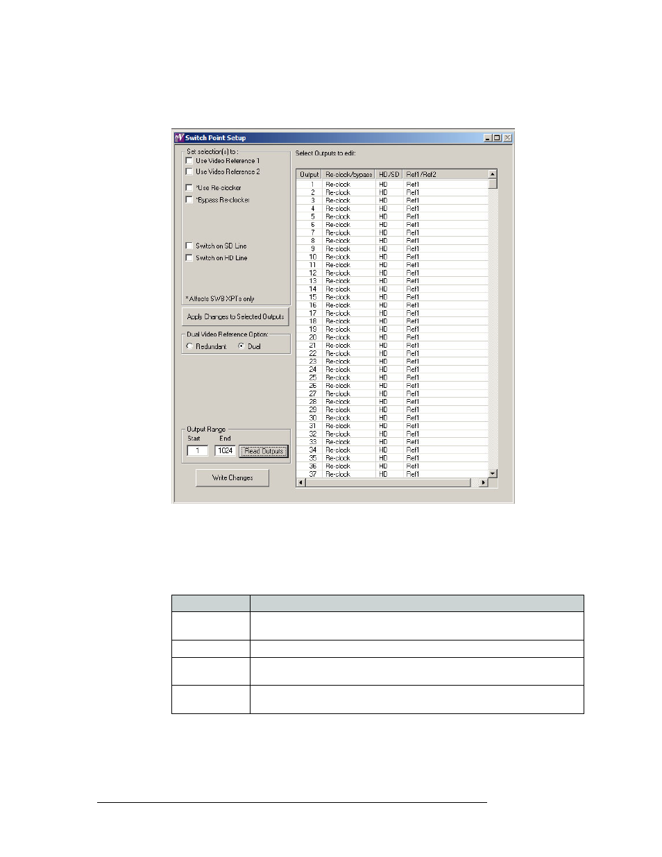
3 From the menu bar, select ‘Window > Switch Point Setup’. The ‘Switch Point Setup’ window
appears displaying current output settings for the router being configured:
Figure 12-8. Switch Point Setup Window
4 In the ‘Output Range’ section, enter a ‘Start’ number of ‘1’ and an ‘End’ number of ‘1024’ and
click
Read Outputs
. Outputs corresponding to the range entered display in the ‘Select Outputs to
edit’ pane with default settings.
The following lists each column and the information it presents:
Column
Description
Output
The number assigned to the signal for internal routing reference purposes. The
number usually refers to the physical port through which the signal is distributed.
Reclock/bypass
Indicates if the signal bypasses re-clocking. See step 5.
HD/SD
Indicates if the signal is a standard definition (SD) or high definition (HD) video
signal. See step 5.
Ref1/Ref2
Indicates if the signal is using the reference signal through ‘VIDEO REF1’ or
‘VIDEO REF2’ connection on the router. See step 5.