Testing machine control ports switching, Managing machine control ports – Grass Valley UniConfi NVISION Series v.1.3 User Manual
Page 120
108
Rev 1.3 • 14 Dec 09
11. Managing Machine Control Ports
Testing Machine Control Ports Switching
5 In the ‘Physical Output Range’ section, enter a ‘Start’ and ‘End’ number in the fields provided
and click
Read Outputs
. The corresponding ports display on the tab.
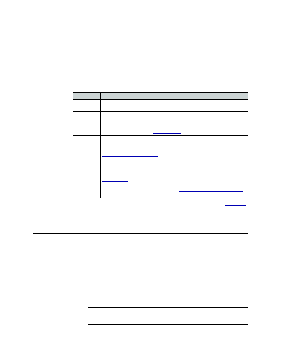
The following lists each column and the information it presents:
If no machine control partitions have been set up, these fields are grayed-out. (See
6 Repeat steps 2–5 for each control card being viewed.
Testing Machine Control Ports Switching
Only the NV5128 and NV5256 routers switch machine control signals. Machine control signals are
neither inputs or outputs, but rather bi-directional. Both routers display a ‘Machine Control’ tab in
the ‘Connections’ window, which lists all machine control ports on the router.
Machine control port routing is tested by performing “takes”. A ‘take’ is a specific moment in time
when signals are switched based on defined parameters. For machine control signals, performing a
‘take’ of multiple signals may not always be practical. For example, performing a ‘Diagonal Take’,
connects port 1 to port 1, port 2 to port 2 and so on. (See
Updating Machine Control Port Switching
on page 110.) When ports are connected to themselves in this manner, the port’s connections are
automatically tri-stated..
Note
When the Machine Control tab is selected, entries in ‘Physical Output Range’
and in ‘Single Take’ fields refer to machine control port numbers, not physical
input or output numbers on the frame.
Column
Description
Input
The number assigned to the signal for internal routing reference purposes. The number
usually refers to the physical port through which the signal is received.
Output
The number assigned to the signal for internal routing reference purposes. The number
usually refers to the physical port through which the signal is distributed.
LPR
Indicates if the configuration has been locked/protected. Locks are set using the router
control system. To unlock, see
Status
The current state of the ports for machine control signals:
Tristate
—
The port is “open” and has no machine control routing directions assigned.
P2P Controlled
—
Indicates that the port is being controlled by another device. See
Setting Up Machine Control Ports
P2P Controlling
—
Indicates that the device is normally a controlling device. See
Setting Up Machine Control Ports
BcastControlling
—
Indicates that a controlling device is broadcasting (sending) signals
to the ports for distribution to controlled (receiving) devices. See
RecvOnlyControlled
—
Indicates that a controlled device is receiving signals from the
ports from a controlling (sending) device. See
Broadcasting Machine Control Signals
Caution
Performing random ‘takes’ on machine control ports may cause unexpected results
if the ports are connected to a variety of equipment throughout your facility.