Version 13.0.3.xx, Version 14.0.0.xx, How to set up a monitor level – Grass Valley UniConfi NVISION Series v.1.3 User Manual
Page 143: 2 select a control card, Nv8500 monitor configuration and operation
UniConfig Configuration Application • User’s Guide
131
13. NV8500 Monitor Configuration and Operation
UniConfig Settings
NV8280/NV8280-Plus and NV8576/NV8576-Plus each have a minimum of two monitor cards:
one for inputs and one for outputs. Therefore, the ‘OUT’ connectors map directly to the same level
in UniConfig.
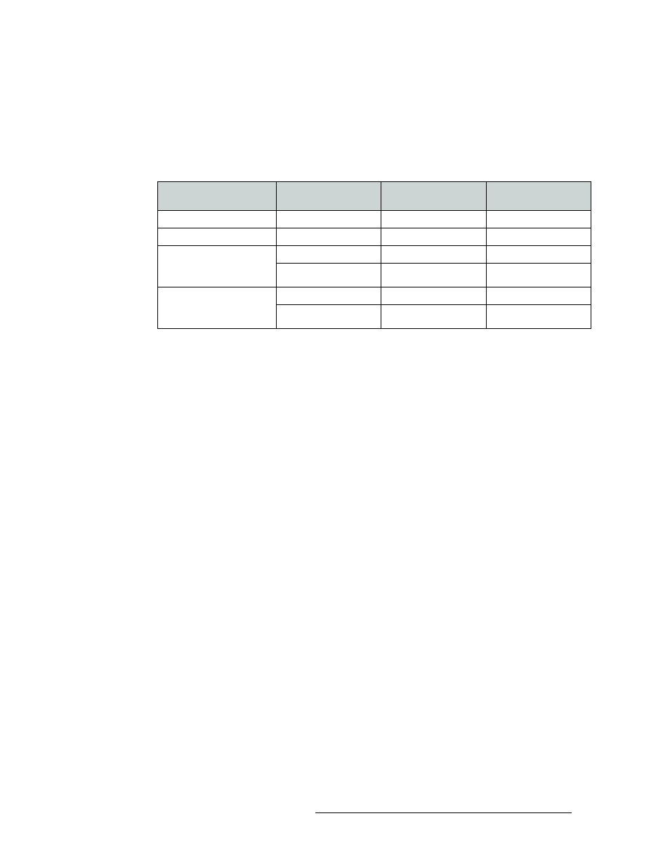
The following lists how for each router, the associated monitor backplane connectors, map to Uni-
config Monitors on the Monitor Page, and to the ports on Monitor Level:
Version 13.0.3.xx
Control cards running control application versions APP, 13.0.3.xx and older support output moni-
tors only (matching FPGA versions: CPLD, SV0900-06, SV0901-05 and older).
Version 14.0.0.xx
Control cards running control application versions APP, 14.0.0.xx and newer support input and out-
put monitors (matching FPGA versions: CPLD, SV0900-07, SV0901-06 and newer).
How to Set Up a Monitor Level
1 Launch UniConfig and establish communication:
a Click on the short-cut on your desktop or from the operating system ‘Start’ menu, select
‘Programs > UniConfig’. Refer to your operating system’s Help system for details.
b Establish communication using an Ethernet or serial connection:
For an Ethernet connection, connect the PC running UniConfig to the RJ45 Ethernet port of
the router and from the menu bar, select ‘Communications > Ethernet’.
Or
For a serial connection, connect the PC running UniConfig to one of the router diagnostic
serial ports and from the menu bar, select ‘Communications > Serial’.
2 Select a control card:
If you are using an Ethernet connection, from the menu bar, select ‘Communications > Ether-
net’. The ‘Control Card’ pane appears. On the ‘Control Cards’ pane, click on the name of a con-
trol card to select it.
Or
If you are using a serial connection:
a From the menu bar, select ‘Communications > Serial’.
b Again, from the menu bar, select ‘Communications > Setup’. The ‘Serial Communications
Setup’ pane appears.
Router Monitor
Monitor Backplane
Connector
UniConfig Monitors
Controller Outputs
NV8144 (Output Monitor)
OUT 1
Monitor 3
3
NV8144 (Input Monitor)
OUT 2
Monitor 1
1
NV8280/NV8280-Plus
NV8576/NV8576-Plus
(Output Monitor)
OUT 1
Monitor 1
1
OUT 2
Monitor 2
2
NV8280/NV8280-Plus
NV8576/NV8576-Plus
(Input Monitor)
OUT 1
Monitor 3
3
OUT 2
Monitor 4
4