Managing partitions and signal types – Grass Valley UniConfi NVISION Series v.1.3 User Manual
Page 71
UniConfig Configuration Application • User’s Guide
59
8. Managing Partitions and Signal Types
Setting Up Partitions
7 Enter a unique ‘Index’ number in the field provided in the ‘Expansion’ section. This number
acts as an identification number in UniConfig. The number must be unique and not assigned to
any other router.
8 To set up a partition, enter ‘Level’, ‘Physical Inputs’, ‘Controller Inputs’, ‘Physical Outputs’
and ‘Controller Output’ information for each switching matrix in the fields provided. Each row
represents one partition (called ‘Level’ on the interface) in the router control system. A total of
four partitions can be created.
For the NV5256, machine control signals must be assigned to a single, individual partition; the
physical inputs and outputs must be on a separate level from other signal types. The physical
input and output ranges should be 1–32 or 1–64, depending on the size of your machine control
partition.
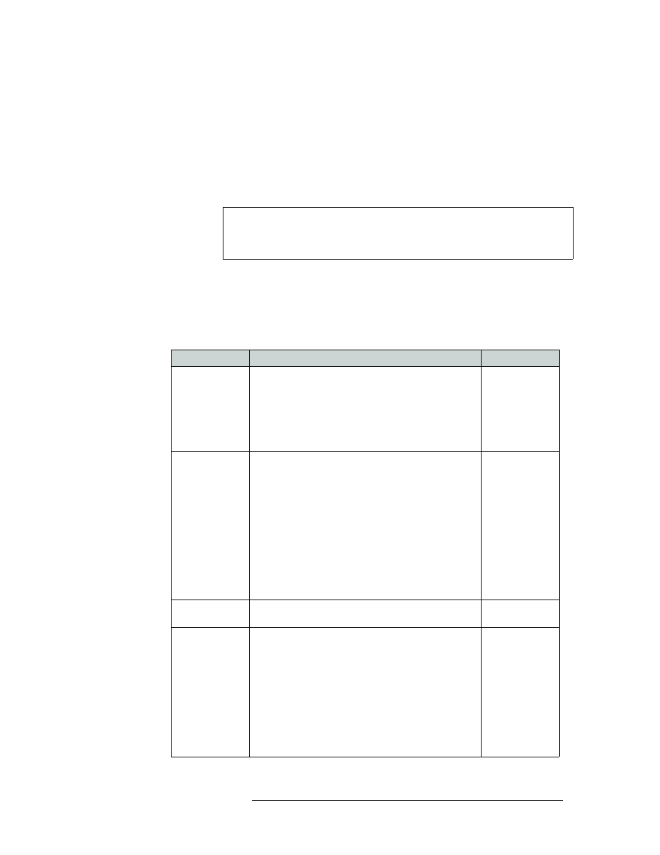
The following is a list of each field and the corresponding information to be entered:
Note
Partitions (also called ‘levels’) must be unique. If a level is not unique, the
router control system has no way of distinguishing one set of crosspoints from
another.
Field
Description
Values
Level
Numeric value identifying a particular configured
partition. This value usually has to match what has been
configured in the control system being used.
Enter a number for the router signal type. If multiple
signal types are managed by the router, enter additional,
unique numbers, one for each signal type, creating a new
row for each signal.
0–250
Physical Inputs
This number dependent on the number of routers
connected together. Refer to step 6 for a list of total inputs.
Input connectors this partition starts and ends with:
NV5256
—
1 through 512 (2 routers)
NV7256-Plus
—
1 through 1,024 (4 routers)
NV7512
—
1 through 2,048 (4 routers)
NV8256-Plus
—
1 through 512 (2 routers)
NV8288-Plus
—
1 through 576 (2 routers)
NV8500 Family:
NV8280-Plus
—
1 through 288
NV8576-Plus
—
1 through 576
1–xxx
Controller Input
Logical number this partition starts with. Typically must
match what control system has been configured to use.
Typically 0 or 1
Physical Outputs
Output connectors this partition starts and ends with:
NV5256
—
1 through 256
NV7256-Plus
—
1 through 256
NV7512
—
1 through 512
NV8256-Plus
—
1 through 256
NV8288-Plus
—
1 through 288
NV8500 Family:
NV8280-Plus
—
1 through 576 (2 routers)
NV8576-Plus
—
1 through 1,152 (2 routers)
1–xxx