Managing partitions and signal types – Grass Valley UniConfi NVISION Series v.1.3 User Manual
Page 70
58
Rev 1.1 • 14 Dec 09
8. Managing Partitions and Signal Types
Setting Up Partitions
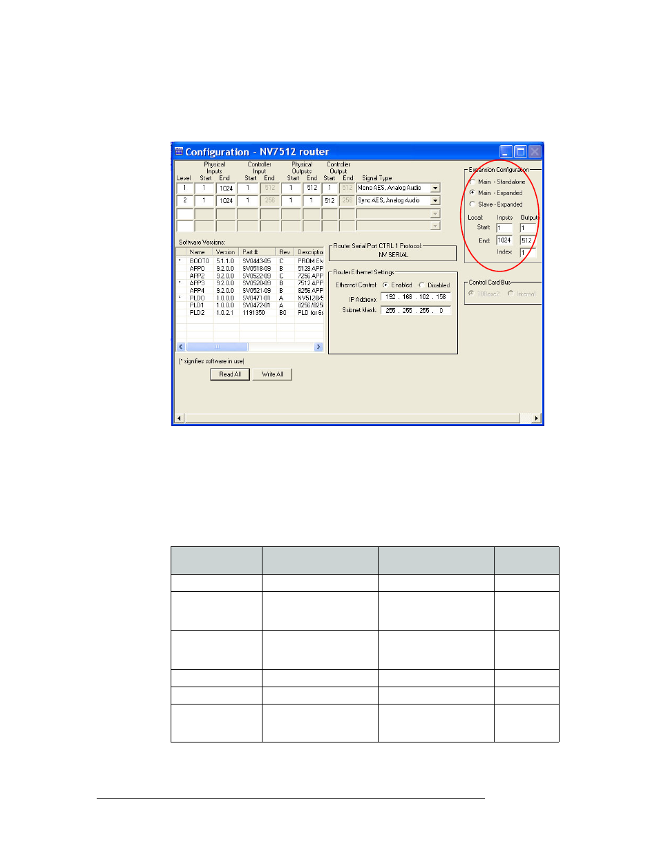
5 Select the ‘Main -Expanded’ radio button in the ‘Expansion’ section. This sets the control card
on the router as the master (or main) control card controlling all slave routers and expands the
‘Expansion’ section:
Figure 8-4. Example of a Configuration Window for Routers with Frame Expansion Section
6 For ‘Local Inputs’ and ‘Outputs’, enter a ‘Start’ and ‘End’ number in the corresponding fields.
The inputs are the total number of signals for all routers. In this example, the NV7512 can man-
age 512 x 512 and is connected to a second 512 x 512 router. This means that the router
receives a total of 1,024 inputs: 512 from the local inputs and 512 from the connected router.
However, the router only distributes local outputs, for a total of 512.
The following lists the maximum number of inputs and outputs for the master router:
Router
Number of Frames That Can
be Connected
Inputs
Outputs
NV5256
2 at 256 ports each
2 routers: 1–512
1–512
NV7256-Plus
4 at 256 × 256 each
2 routers: 1–512
3 routers: 1–768
4 routers: 1–1,024
1–256
NV7512
4 at 512 × 512 each
2 routers: 1–1,024
3 routers: 1–1,536
4 routers: 1–2,048
1–512
NV8256-Plus
2 at 256 × 256
2 routers: 1–512
1–256
NV8288-Plus
2 at 288 × 288
2 routers: 1–576
1 –288
NV8500 Family:
NV8280-Plus
NV8576-Plus
2 at 288 x 288
2 at 576 x 576
2 routers: 1–576
2 routers: 1–1,152
1–576
1–1,152