Nv8500 monitor configuration and operation – Grass Valley UniConfi NVISION Series v.1.3 User Manual
Page 146
134
Rev 1.3 • 14 Dec 09
13. NV8500 Monitor Configuration and Operation
Using Partitioning Addressing
For specific ‘take’ command formats, refer to the following Miranda NVISION protocol docu-
ments:
NP0016
—
NVISION Ethernet Protocol Router Control Messages
NP0010
—
NVISION Serial Protocol Router Control Messages
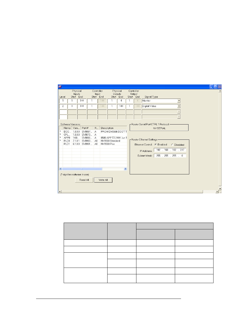
Figure 13-3 shows how partition values as displayed in UniConfig. These values are valid for any
NV8500 Family router. In this example, ‘Physical Inputs’ and ‘Physical Outputs’ map one-to-one
to the ‘Controller Inputs’ and ‘Controller Outputs’. Level 1 controls switching of the router’s inputs
or outputs through the monitor card. Level 2 controls standard crosspoint switching.
Figure 13-3. Example of UniConfig with Partition Values
For a Monitor Level, ‘Controller Inputs’ and ‘Controller Outputs’ map to the following:
• ‘Controller Inputs’ can be any of the router’s inputs or outputs to be monitored.
• ‘Controller Outputs’ map directly to the Monitor card ‘OUT’ connectors as shown:
Router Monitor
Controller Inputs
Controller Output to Monitor Card Connector Map
Controller Outputs
Monitor Card Backplane
Connector
NV8144 (Output Monitor)
outputs
3
OUT 1
NV8144 (Input Monitor)
inputs
1
OUT 2
NV8280/NV8280-Plus
NV8576/NV8576-Plus
(Output Monitor)
outputs
1
OUT 1
outputs
2
OUT 2
NV8280/NV8280-Plus
NV8576/NV8576-Plus
(Input Monitor)
inputs
3
OUT 1
inputs
4
OUT 2