Testing input/output switching ‘takes, Standard signals, How to test standard switching configurations – Grass Valley UniConfi NVISION Series v.1.3 User Manual
Page 107: 4 select the ‘x-y/standard’ tab, Managing inputs and outputs
UniConfig Configuration Application • User’s Guide
95
10. Managing Inputs and Outputs
Testing Input/Output Switching ‘Takes’
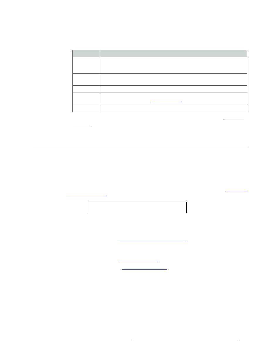
The following lists each column and the information it presents:
If no mono audio partitions have not been set up, these fields are grayed-out. (See
6 Repeat steps 2–5 for each control card being viewed.
Testing Input/Output Switching ‘Takes’
Using the UniConfig ‘Connections’ window, current switching matrix can be tested. Testing is
accomplished by performing a series of ‘takes’. A ‘take’ is a specific moment in time when signals
are switched based on defined parameters. Both standard and mono switching configurations can
be tested.
For information on testing machine control signals for the NV5128 and the NV5256, see
Standard Signals
The ‘X-Y/Standard’ tab displays for all routers except the NV5256. If no partitions have been set
up, this tab is inactive. (See
Managing Partitions and Signal Types
How to Test Standard Switching Configurations
1 Launch UniConfig. (See
2 Select a control card. (See
3 From the menu bar, select ‘Window > Connections’. The ‘Connections’ window appears with
blank fields. (See Figure 10-6 on page 93.)
4 Select the ‘X-Y/Standard’ tab.
5 In the ‘Physical Output Range’ section, enter a ‘Start’ and ‘End’ number in the fields provided.
6 Click
Read Outputs
. The corresponding inputs and outputs display on the tab, as shown in
Figure 10-6 on page 93. The current router switching configuration displays.
The ‘Connections’ window displays all crosspoints in a router as one large set whereas the
‘Configuration’ window displays each partition separately.
Column
Description
Mono
The number assigned to the signal for internal routing reference purposes. For example,
the left channel of stereo signal 1 (listed in the ‘Phys’ column) is assigned number 1 and
the right channel is assigned number 2.
Phys
The physical signal being received or distributed. A stereo audio signal is comprised of
two channels: one left and one right.
Chnl
The signal number assigned to the left channel or right channel of the physical signal.
LPR
Indicates if the configuration has been locked/protected. Locks are set using the router
control system. To unlock, see
Status
Mono takes are reported as a breakaway in the ‘Status’ column on the tab.
Note
Each control card must be tested separately.