Broadcasting machine control signals, How to broadcast signals, Broadcasting machine – Grass Valley UniConfi NVISION Series v.1.3 User Manual
Page 124: Control signals, Managing machine control ports
112
Rev 1.3 • 14 Dec 09
11. Managing Machine Control Ports
Broadcasting Machine Control Signals
Broadcasting Machine Control Signals
UniConfig enables you to “broadcast” signals from one device, through the router, out to one or
more connected devices. To set up broadcasting, two steps must be performed. First, bi-directional
communication is set up between the Controlling device and one of the Controlled devices. This
allows the Controlled device to return a status indicating if commands received from the Control-
ling device are being performed. Next, single direction communication is set up between the Con-
trolling device and all other Controlled devices. This enables the commands to be sent from the
Controlling device to many other Controlled devices without having to receive multiple status
reports; all status reporting is through the first Controlled device.
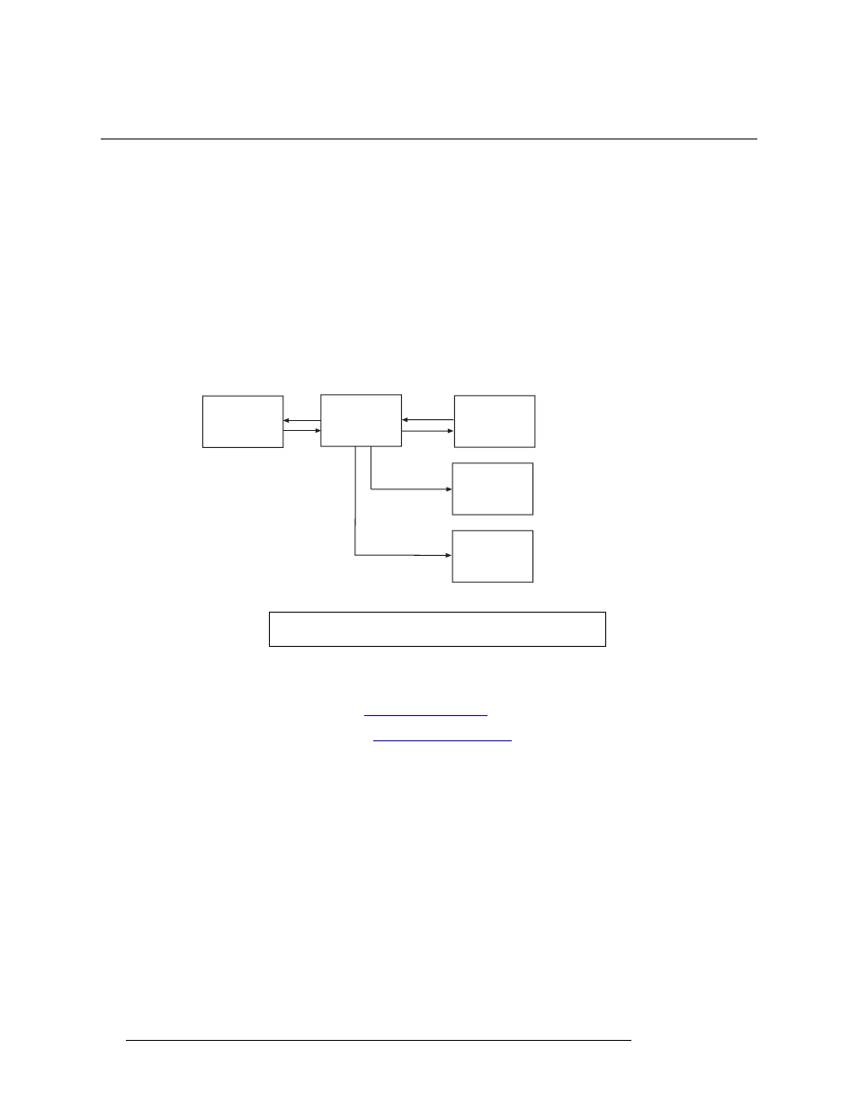
Figure 11-6 shows Device A as the Controlling device routing data to Device B, Device C, and
Device D. Device B sends a status back to Device A. Device A forwards information to all other
devices, but only Device B can send information in reverse.
Figure 11-6. Broadcasting from Device A to Devices B, C, and D.
How to Broadcast Signals
1 Launch UniConfig. (See
2 Select a control card. (See
3 Select the ports that will act as Controlling and as Controlled:
a From the menu bar, select ‘Window > Machine Control Port Setup’. The ‘Machine Control
Port Setup’ window appears displaying current port settings, as shown in Figure 11-1.
b Click
Read
, or from the menu bar, select ‘Edit >Read All’. The current configuration of each
of the ports displays in the right-hand pane with default settings.
c Enter a number in the ‘Take Delay’ field to set the frame ‘take’ delay. The “take delay” is
the number of video frames between the time a port is disconnected from one device and
connected to another. The delay period should be long enough to allow devices to recognize
Device A
Device D
Device C
Device B
Router
Data
Data
Data
Data
Status
Status
Note
Each control card must be configured separately.